Lined Butterfly Valve

A butterfly valve and lining type technology, which is applied in the direction of lifting valves, valve devices, mechanical equipment, etc., can solve the problems of secondary leakage, primary leakage, poor tightness, etc., and achieve the effect of improving shaft sealing and preventing leakage

Active Publication Date: 2019-06-25
KITZ CORP
View PDF8 Cites 0 Cited by
  • Summary
  • Abstract
  • Description
  • Claims
  • Application Information

AI Technical Summary

Problems solved by technology

In this case, the upper and lower sides of the resin lining layer 3 are biased toward the secondary side with respect to the resin valve seat ring 5 , and the adhesiveness is deteriorated. The airtightness of the surrounding valve rod 6 and the valve box 9, that is, the airtightness of the air and earth is reduced, and so-called primary leakage may occur.
[0026] Furthermore, in Figure 9 In the process, as the valve body 4 moves, the valve rod 6 moves to the secondary side, and thus the adhesiveness between the valve rod covering part 7 and the extension covering part 8 also deteriorates, and the valve rod covering part 7 and the extension covering part 8 The sealing performance between the valve rod 6 and the valve box 9, that is, the shaft sealing performance of the valve rod 6 is reduced, and so-called secondary leakage may occur.

Method used


Image

  • Lined Butterfly Valve
  • Lined Butterfly Valve
  • Lined Butterfly Valve

Examples


Embodiment Construction

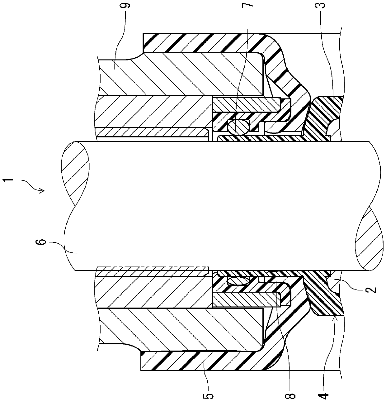
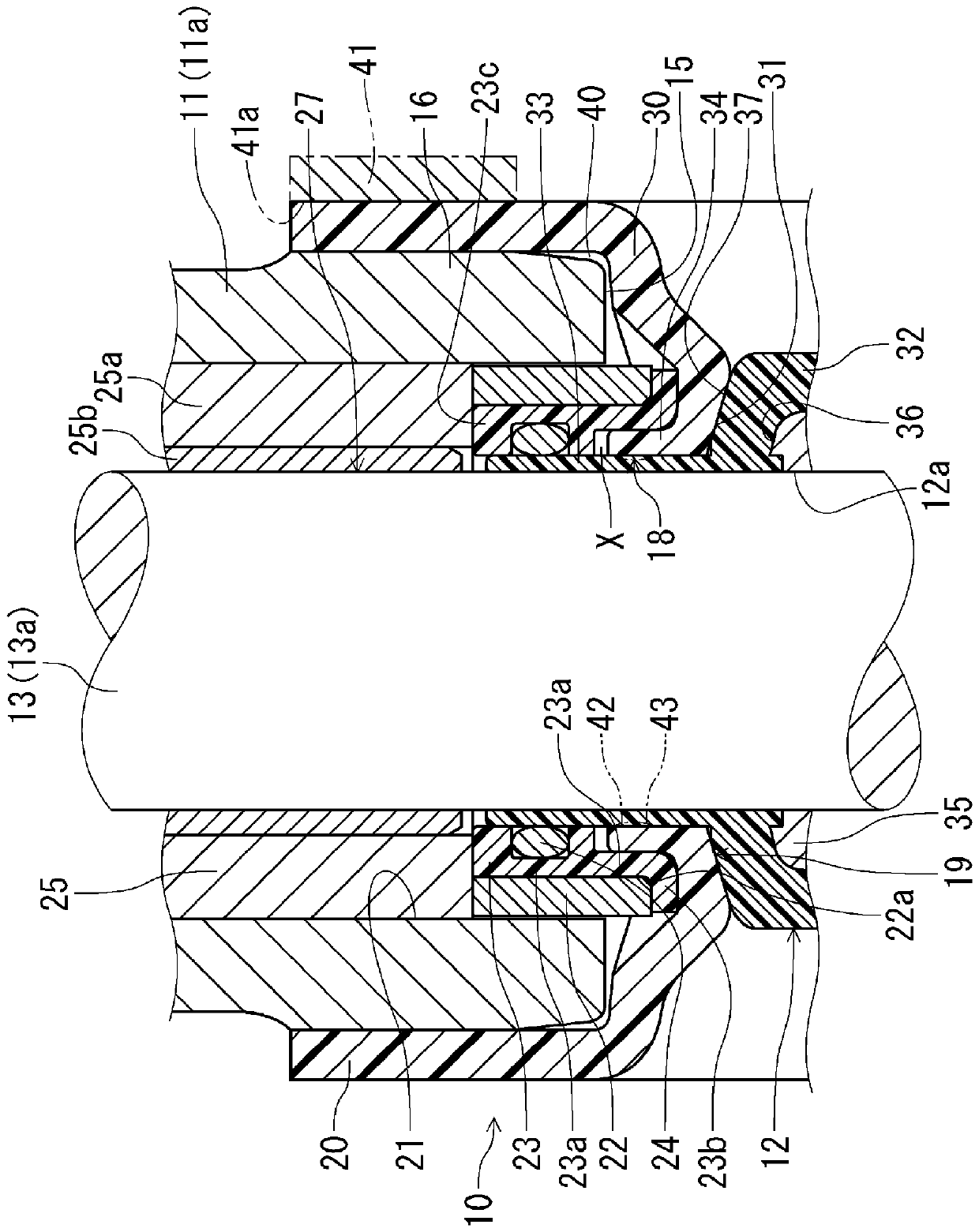
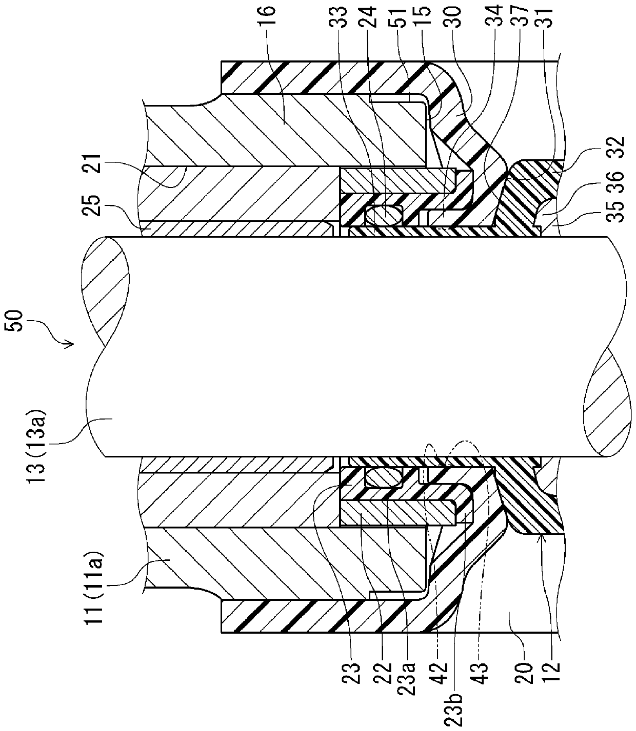
[0093] Hereinafter, embodiment of the liner type butterfly valve of this invention is demonstrated in detail based on drawing. exist figure 1 , figure 2 In, represents the embodiment of the butterfly valve of the present invention, in image 3 in, means figure 2 An enlarged sectional view of the main part.

[0094] exist figure 1 , figure 2Among them, the butterfly valve (hereinafter referred to as the valve body 10) is used, for example, in chemical industry facilities or food-related pipelines, and has a cylindrical valve body 11, a valve disc 12, an upper valve stem 13a and a lower valve body. The stem 13 constituted by the stem 13b is provided with a nominal diameter of 100A. As will be described later, in the valve main body 10, there are provided a cylindrical lining portion 34 having the valve seat lining 20, a shaft cylinder lining portion 33 of the lining portion 32, a shaft sealing portion 18 of the sealing bush 23, and a cylindrical lining portion 34 havi...


PUM


Abstract

To provide a butterfly valve, which is a liner type butterfly valve with corrosion resistance to fluids, which can simultaneously improve air-to-earth sealing and shaft sealing to reliably prevent leakage. They maintain their tightness even when moving. A valve disc (12) covered by a liner (32) is provided in a cylindrical valve body (11) covered by a seat liner (20) to open and close via a valve stem (13). Clamp the shaft sealing part (18) of the valve stem (13) between the ring body (22) and the valve stem (13), thereby preventing the diameter expansion of the shaft sealing part (18), and using the The rebound force of the spring (44) in the shaft mounting part (27) of (11) pushes the valve seat lining (20) on the boss surface (37) of the valve disc (12) through the ring body (22), This maintains the airtightness of the sky-earth seal ( 19 ).

Description

technical field [0001] The present invention relates to a liner type butterfly valve with a resin lining on the inner peripheral surface of a valve body and a valve box, and in particular to a butterfly valve with improved airtightness near the air and earth side of the valve body and the shaft sealing portion of the valve rod. Background technique [0002] Conventionally, as butterfly valves used in facilities for the chemical industry where highly corrosive fluids flow, or in food-related flow paths, etc., it is known that a metal core of the valve body is A butterfly valve with a so-called liner structure is covered with a resin liner layer and a resin seat ring is mounted on the inner peripheral surface of the valve box. The body lining layer and resin valve seat ring of this lined butterfly valve are made of resin materials such as PTFE or PFA. Other than these materials, they are not in contact with fluids, so they are suitable for severe corrosive fluids, chemical flu...

Claims


Application Information

Patent Timeline
Patent Type & Authority Patents(China)
IPC IPC(8): F16K1/226
CPCF16K1/226F16K1/2265F16K1/2268
Inventor 邱明平仲川博明
Owner KITZ CORP
Why Eureka
Try Eureka