Light beam direction controlling element and display device

A technology of direction control and light beam, which is applied in the direction of optical components, identification devices, installation, etc., to achieve the effect of reducing productivity and suppressing warpage

Inactive Publication Date: 2017-09-26
TIANMA MICRO ELECTRONICS CO LTD
View PDF9 Cites 4 Cited by
  • Summary
  • Abstract
  • Description
  • Claims
  • Application Information

AI Technical Summary

Problems solved by technology

However, light incident at large angles relative to the orientation of the louvers, or light incident obliquely on the surface of the film, is absorbed by the louvers and therefore cannot pass through them.

Method used


Image

  • Light beam direction controlling element and display device
  • Light beam direction controlling element and display device
  • Light beam direction controlling element and display device

Examples


Embodiment approach 1

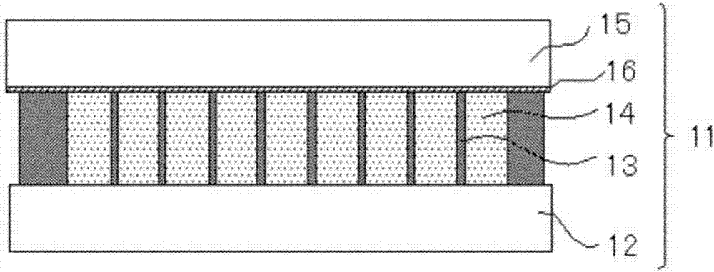
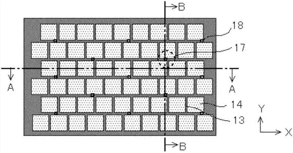
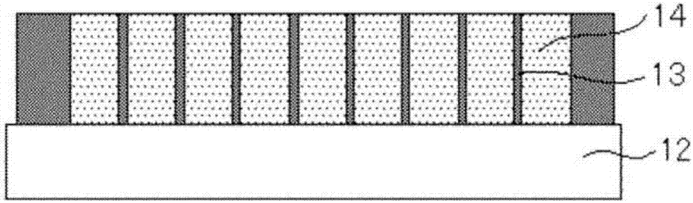
[0057] figure 1 It is a sectional view showing the structure of the light beam direction control element (ultrafine louver) according to the first embodiment of the present invention. Figure 2A is the top view of the beam direction control element, Figure 2B is a sectional view taken along the line A-A, Figure 2C It is a cross-sectional view taken along line BB. According to the beam direction control element 11 of the present embodiment, the light-absorbing regions 13 made of a light-absorbing material and the light-transmitting regions 14 made of a light-transmitting material are alternately arranged on a transparent substrate 12 (with The light-transmitting region 14 on the top and the light-absorbing region 13 filling the gap between the light-transmitting regions 14), another transparent substrate 15 is laminated on the transparent substrate 12 via an adhesive 16 and bonded to the transparent substrate 12.

[0058] In the light beam direction control element 11, am...

Embodiment approach 2

[0071] Now, will refer to Figure 5A and Figure 5B A second embodiment of the present invention will be described. The beam direction control element according to the second embodiment and Figure 1 to Figure 3 Similar to the illustrated beam direction control element according to the first embodiment, in order to bend the light-absorbing region 13, the shape and arrangement pattern of the light-transmitting region 14 are changed.

[0072] Figure 5A is a top view of a beam direction control element according to a second embodiment, Figure 5B It is a sectional view taken along line C-C. The present embodiment is characterized in that patterns of different shapes are used as the light-transmitting regions 14 , and the bent portion 17 of the light-absorbing region 13 is formed by proper arrangement of the light-transmitting regions 14 . Therefore, there is no need for a pattern including the specific structure 18 like the first embodiment. As a method of manufacturing th...

Embodiment approach 3

[0075] now refer to Figure 6 A third embodiment of the present invention will be described. Figure 6 is a plan view of the beam direction control element according to the third embodiment. According to the beam direction control element of the third embodiment, by using the first embodiment and the second embodiment (specifically, Figure 1 to Figure 3 The pattern of the structures 18 in the shown first embodiment) as a base for bending the light-absorbing regions 13 has a closed configuration of the light-absorbing regions 13 with respect to the X-direction and the Y-direction (i.e., a closed configuration in which the light-absorbing regions are separated by the structures 18). pattern). In this case, stress distribution due to thermal contraction of the light absorbing material 23 is also attempted, whereby concentration and accumulation of stress in a specific linear direction (X direction or Y direction) can be prevented, and warpage on the transparent substrate 12 ca...


PUM

PropertyMeasurementUnit
refractive indexaaaaaaaaaa

Abstract

Provided are a light beam direction controlling element and a display device configured such that warpage due to the thermal contraction of a light absorbing material is minimized, and such that adhesion between transparent substrates is enhanced, thereby improving reliability without decreasing productivity. The light beam direction controlling element comprises light transmission regions composed of a light transmission material arrayed on a substrate, and light absorbing regions composed of a light absorbing material filled in the gaps between the light transmission regions, the light absorbing regions restricting the direction of the light beam passing through the substrate. The light absorbing regions extend on the substrate surface in a first direction and a second direction orthogonal to each other. The light absorbing regions extending in the first direction and the light absorbing regions extending in the second direction intersect each other to have an L-shaped or a T-shaped intersected portion, while having at least one structure that divides the light absorbing regions in the regions extending in the first direction or in the second direction excluding the intersected portion.

Description

technical field [0001] The present invention relates to a light beam direction control element (microlouver: ultra-fine louver) for controlling the directivity of emitted light, and a display device including the light beam direction control element. Background technique [0002] In recent years, liquid crystal display devices have been widely used as display devices for various devices such as flat panel televisions, personal digital assistants (PDAs), and notebook personal computers. In particular, mobile information terminals that are easy to carry around can be used when the display screen of the mobile information terminal is shared by multiple people during meetings or the like, or when information is input in public places such as trains or airplanes. In this way, the mobile information terminal is used under various environmental conditions. [0003] Here, in the shared use environment in the former example, it is preferable that the screen of the mobile information...

Claims


Application Information

Patent Timeline
Patent Type & Authority Applications(China)
IPC IPC(8): G02B5/00G09F9/00B29C65/48
CPCG02B5/003G02B2207/123G02F1/133512G02F1/133524G02B7/008
Inventor 冈本守
Owner TIANMA MICRO ELECTRONICS CO LTD
Why Eureka
Try Eureka