Ballastless-track-slab die

A ballastless track and track plate technology, used in molds, mold trays, mold panels, etc., can solve problems such as the dislocation of the track plate and the track plate, and the edge of the track plate is prone to curling, etc. the effect of leaking

Pending Publication Date: 2017-09-29
TIANJIN YINLONG HIGH TECH NEW MATERIAL RES INST
View PDF4 Cites 4 Cited by
  • Summary
  • Abstract
  • Description
  • Claims
  • Application Information

AI Technical Summary

Problems solved by technology

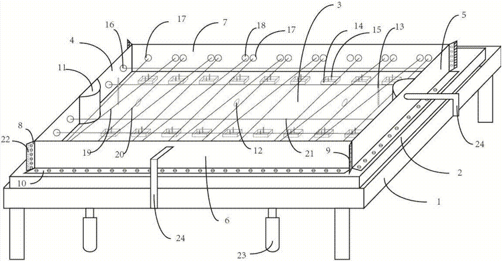
[0003] However, the current connection between the track plates is to install a round table in the groove between the left and right ends to prevent the track plate from moving back and forth, but after a long time, the edge of the track plate is prone to curling, and the track plate There will be misalignment with the track slab, and the strength and sealing of the current track slab are somewhat improved. For this reason, the present invention proposes a ballastless track slab mold, which changes the structure of the track slab by changing the structure of the mold

Method used


Image

  • Ballastless-track-slab die
  • Ballastless-track-slab die

Examples


Embodiment Construction

[0019] The technical solutions of the present invention will be clearly and completely described below in conjunction with the accompanying drawings. Apparently, the described embodiments are some of the embodiments of the present invention, but not all of them. Based on the embodiments of the present invention, all other embodiments obtained by persons of ordinary skill in the art without making creative efforts belong to the protection scope of the present invention.

[0020] In the description of the present invention, it should be noted that the terms "center", "upper", "lower", "left", "right", "vertical", "horizontal", "inner", "outer" etc. The indicated orientation or positional relationship is based on the orientation or positional relationship shown in the drawings, and is only for the convenience of describing the present invention and simplifying the description, rather than indicating or implying that the referred device or element must have a specific orientation, ...


PUM


Abstract

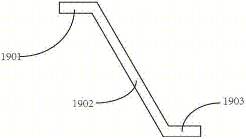
The invention provides a ballastless-track-slab die. The ballastless-track-slab die comprises a bottom die and a rectangular cavity defined by left and right end dies and front and back side dies. The rectangular cavity is used for manufacturing a track slab, a bottom die slab is fixedly installed on a bottom die frame, and the bottom die frame is fixedly installed on a base; the lower extended sections of the left and right end dies and the front and back side dies are connected with the bottom die through bolts, the left extended sections and the right extended sections of the left and right end dies and the left extended sections and the right extended sections of the front and back side dies are connected correspondingly through bolts, and fastener bolt-hole embedded parts are transversely and symmetrically installed in a bearing-rail-bed preformed groove; and a track-slab connecting bolt-hole embedded part is vertically installed in a track-slab connecting preformed hole, semi-circle terrace dies are arranged in the middles of the inner side walls of left and right end die slabs, a plurality of longitudinal prestress stretch-draw-rod mounting holes are further formed in the left and right end die slabs, and a plurality of transverse prestress stretch-draw-rod mounting holes and slant prestress stretch-draw-rod mounting holes are formed in side die slabs. According to the ballastless-track-slab die, the airtightness is good, and the high-strength and firmly and stably connected track slab can be manufactured.

Description

technical field [0001] The invention relates to the technical field of molds, in particular to a ballastless track slab mold. Background technique [0002] The continuous improvement of train speed has put forward new requirements for the track structure of high-speed railways. The ballastless track structure was born under this form. The ballastless track has the characteristics of track stability, uniform rigidity, good durability, and high ride comfort. , significantly reduced maintenance workload and other outstanding advantages. At present, my country usually adopts precast concrete slab ballastless track technology. Its main structural features are: less on-site concrete construction and fast progress; Strong repairability. [0003] However, the current connection between the track plates is to install a round platform in the groove between the left and right ends to prevent the track plates from moving back and forth, but after a long time, the edges of the track plate...

Claims


Application Information

Patent Timeline
Patent Type & Authority Applications(China)
IPC IPC(8): B28B7/00B28B7/16B28B7/12B28B23/04
CPCB28B7/0011B28B7/0055B28B7/12B28B7/164B28B23/04
Inventor 谢志峰
Owner TIANJIN YINLONG HIGH TECH NEW MATERIAL RES INST
Why Eureka
Try Eureka