Airborne smoke bar spreading device

A technology of flame rods and shells, which is applied in the field of airborne flame rod spreading devices, can solve problems such as complicated installation process, reduced applicability, and easy damage to the installation position, and achieve the goals of enhanced universal applicability, reduced local stress, and reduced wind resistance Effect

Pending Publication Date: 2019-07-16
CHINESE ACAD OF METEOROLOGICAL SCI +1
View PDF0 Cites 0 Cited by
  • Summary
  • Abstract
  • Description
  • Claims
  • Application Information

AI Technical Summary

Problems solved by technology

[0002] The airborne flame strip spreading device can artificially affect the weather by spreading silver iodide flame strips, and realize artificial rainfall and artificial hail prevention. At present, the most common airborne flame strip spreading device is cylindrical in shape, and is mostly installed under the engine room, and the interior of the cylinder is arranged For several flame rods, the installed flame rods are limited to one or a few types, and the installation of flame rods generally includes multiple steps such as plugging, fixing, electrode arrangement, etc., and the installation process is complicated
Due to the large overall weight of the cylindrical airborne flame spreading device, the installation position on the aircraft is concentrated and the installation position is easily damaged. In addition, the relatively large volume of the cylindrical airborne flame spreading device leads to The wind resistance is relatively large, which further aggravates the damage process of the installation location. Moreover, the current airborne flame strip spreading device is mostly used on low-speed aircraft due to its large gravity and volume. Slow flight speed will seriously affect its operating efficiency and lead to serious consequences, and only a limited number of silver iodide flame rods can be used, which will greatly reduce its applicability. In addition, most airborne flame rod spreading devices can only spread flame rods, but cannot spread other flame rods such as hexachloroethane-zinc oxide mixture, titanium tetrachloride, sulfur trioxide-chlorosulfonic acid mixture, etc., which further reduces the range of use of the airborne flame rod spreading device

Method used


Image

  • Airborne smoke bar spreading device
  • Airborne smoke bar spreading device
  • Airborne smoke bar spreading device

Examples


Embodiment 1

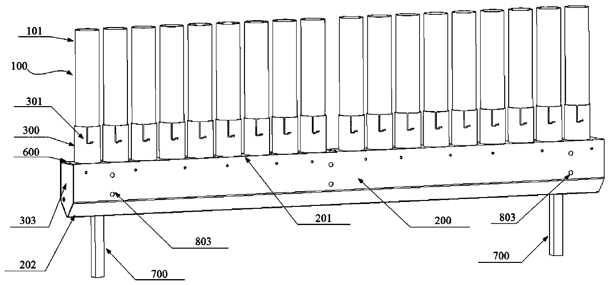
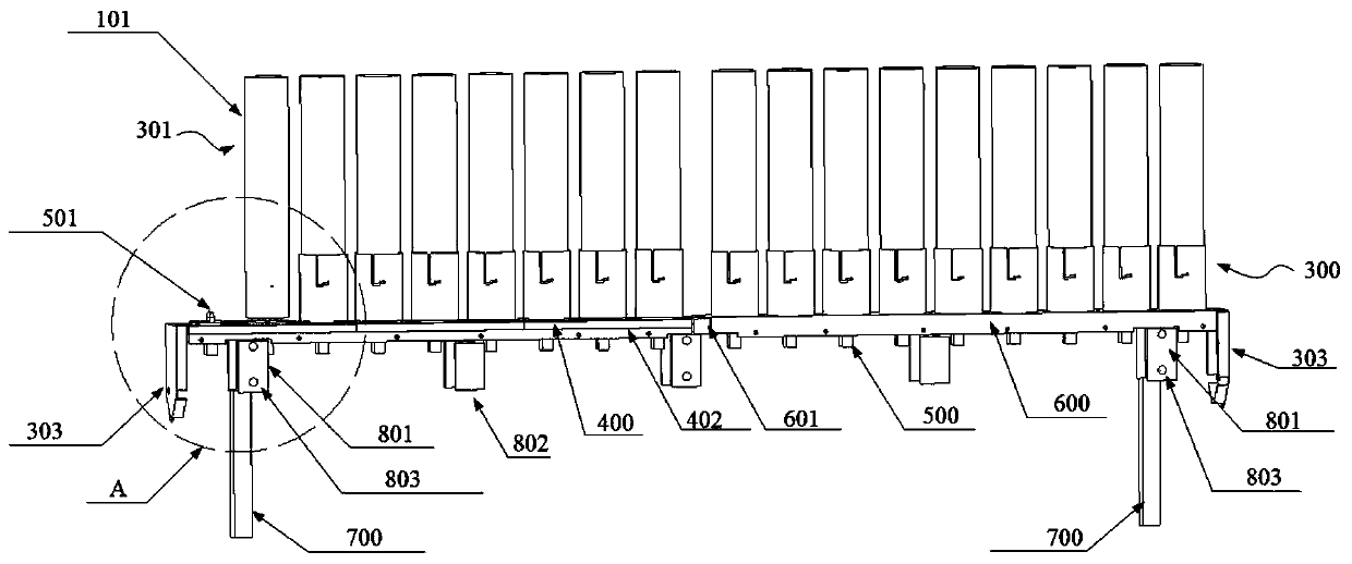
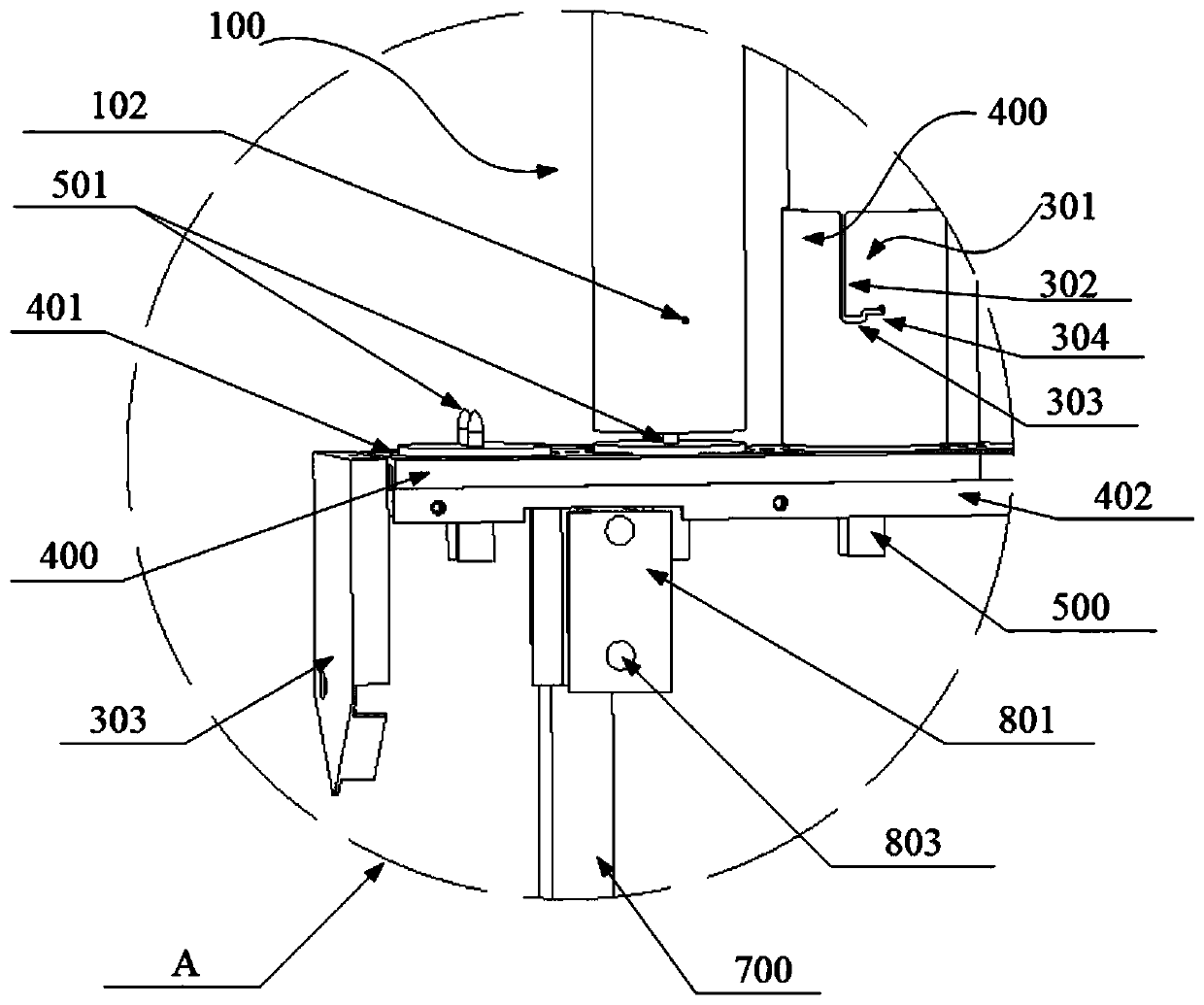
[0034] Such as Figure 1-3As shown, an airborne flame rod spreading device in this embodiment includes several flame rods 100, a spreading housing 200, several flame rod tubes 300, several flame rod tube bases 400, several end covers 600, several fixing plates 402, A number of spring structures 500, a number of positive and negative electrode columns, a V-shaped end cap 203, a number of first support plates 801, a number of second support plates 802, and a number of brackets 700, and a number of flame bars 100 are parallel to each other and spaced in a "one" shape Arranged in a row, the flame rod 100 is provided with a number of positioning pins 102, and the flame rod tube 300 is provided with a number of limiting grooves 301, and the positioning pins 102 are inserted into the limiting grooves 301 and rotated at a certain angle The locating pin 102 is snapped into the limiting groove 301, the flame bar base 400 is provided with a plurality of circular grooves 401, the end cove...


PUM


Abstract

The invention relates to an airborne smoke bar spreading device. The airborne smoke bar spreading device comprises a plurality of smoke bars and a spreading shell body; the multiple smoke bars are installed on the spreading shell body, and the multiple smoke bars are parallel to each other and are arranged and distributed into a linear row in a spaced mode; due to the fact that the multiple smokebars fixed to the spreading shell body are parallel to each other and arranged and distributed into the linear row in a spaced mode, so that the structure can effectively reduce wind drag, and the structure can be applied to a high-speed airplane; in addition, structurally, the airborne smoke bar spreading device can be divided into a plurality of similar areas, the areas enable the gravity of theairborne smoke bar spreading device be in a dispersed distributed state, namely, the gravity of the airborne smoke bar spreading device of the structure is not concentrated on a certain point or in several limited areas, so that the local stress of an installing position on the airplane is greatly reduced, and damage is reduced; and furthermore, smoke bars of various specifications and differentfunctions can be adopted, and the general applicability of the airborne smoke bar spreading device can be further enhanced.

Description

technical field [0001] The invention relates to an airborne flame rod spreading device, in particular to an airborne flame rod spreading device with low wind resistance, universal applicability and strong strength. Background technique [0002] The airborne flame strip spreading device can artificially affect the weather by spreading silver iodide flame strips, and realize artificial rainfall and artificial hail prevention. At present, the most common airborne flame strip spreading device is cylindrical in shape, and is mostly installed under the engine room, and the interior of the cylinder is arranged For several flame rod tubes, the installed flame rods are limited to one or a few types, and the installation of flame rods generally includes multiple steps such as plugging, fixing, electrode arrangement, etc., and the installation process is complicated. Due to the large overall weight of the cylindrical airborne flame spreading device, the installation position on the air...

Claims


Application Information

Patent Timeline
Patent Type & Authority Applications(China)
IPC IPC(8): B64D1/02B64D47/00B64C39/02A01G15/00
CPCA01G15/00B64C39/02B64D1/02B64D47/00
Inventor 李宏宇高扬马振营
Owner CHINESE ACAD OF METEOROLOGICAL SCI
Why Eureka
Try Eureka