Engine valve device

An engine valve and valve technology, which is applied to engine components, machines/engines, valve devices, etc., can solve problems such as poor valve sealing, and achieve the effects of avoiding wear, improving sealing, and reducing local stress.

Inactive Publication Date: 2012-04-11
ZHEJIANG CFMOTO POWER CO LTD
View PDF6 Cites 4 Cited by
  • Summary
  • Abstract
  • Description
  • Claims
  • Application Information

AI Technical Summary

Problems solved by technology

[0004] In view of this, the purpose of the embodiment of the present invention is to provide an engine valve device, which can make the valve rod freely rotate around the valve rod axis by rationally improving the traditional valve device, so as to solve the problem of engine compression and work process. Valve sealing problem

Method used


Image

  • Engine valve device
  • Engine valve device
  • Engine valve device

Examples


Embodiment Construction

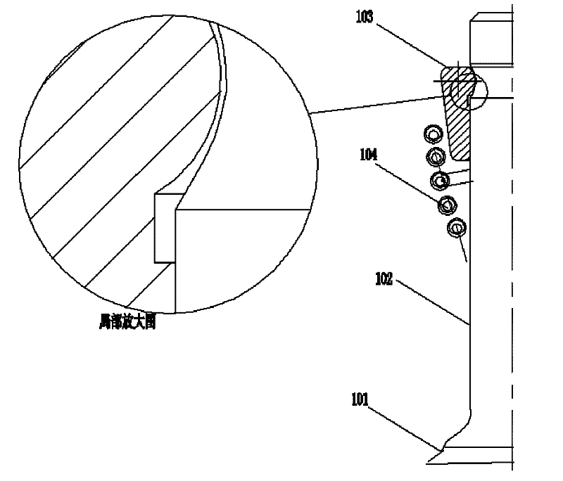
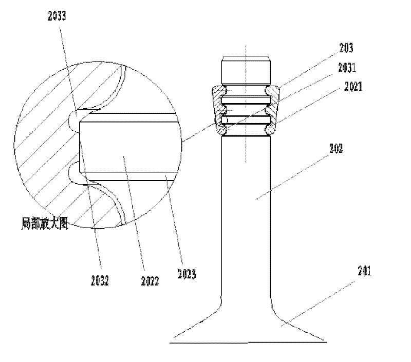
[0016] The embodiment of the present invention reforms the traditional engine valve device. At least three lock clip grooves are arranged on the upper end of the valve stem. The lock clip grooves are separated by convex belts. At the same time, a corresponding structure is set in the valve lock clip, the height of the convex surface is less than the groove depth of the lock clip groove; the diameter of the convex surface band is smaller than the diameter of the concave surface band, using this valve structure, even under the action of the spring lock When the clamp is locked on the valve stem, the valve stem can still rotate freely around the axis of the valve stem, thereby better sealing the cylinder and solving the problem of air leakage in the process of engine compression and work in the prior art.

[0017] In order to understand the purpose and technical characteristics of the present invention more clearly, the present invention will be further described in detail below i...


PUM


Abstract

The embodiment of the invention provides an engine valve device. The device comprises a valve, a valve rod and a valve lock clip, wherein the lower end of the valve rod is connected with the valve; at least three lock clip grooves are arranged on the upper end of the valve rod; convex bands are arranged at intervals among the lock clip grooves, two edges of each convex band are crossed with the edges of each lock clip groove through a slope surface; the inner side of the valve lock clip comprises at least three convex edge surfaces which are corresponding to the lock clip grooves; concave bands corresponding to the convex bands are arranged at intervals among the convex edge surfaces; two edges of each concave band are connected with the root part of each convex edge surface through small grooves; the height of each convex edge surface of the valve lock clip is less than the depth of each lock clip groove; and the diameter of each convex band is less than that of each concave band. In the embodiment of the invention, the valve rod can rotate around the axis of the valve rod under the action of a spring so as to prevent air leakage.

Description

technical field [0001] The invention relates to the technical field of engine intake and exhaust systems, in particular to an engine valve device. Background technique [0002] An engine is a complex system of multiple components that converts thermal energy into mechanical energy. Heat energy is generated by the mixed combustion of the air sucked into the cylinder from the outside and the oil sprayed into the cylinder by the fuel injector. After a large amount of heat is generated, the pressure in the cylinder suddenly increases, thereby pushing the piston to reciprocate to do work, and the heat energy is converted into mechanical energy. After the combustion is completed , the exhaust gas in the cylinder is discharged through the valve. Intake and exhaust are important links in the four working strokes of the engine. Air is inhaled by opening the intake valve during intake, and exhaust gas is discharged by opening the exhaust valve during exhaust. The doors are closed to...

Claims


Application Information

Patent Timeline
Patent Type & Authority Applications(China)
IPC IPC(8): F01L3/00
Inventor 赖国贵袁章平郭彦炜阳远贵魏勇平
Owner ZHEJIANG CFMOTO POWER CO LTD
Why Eureka
Try Eureka