High-power fiber laser safety monitoring method and device

A fiber laser, safety monitoring technology, used in measuring devices, optical instrument testing, machine/structural component testing, etc. It can solve the problem that the internal temperature is difficult to observe, the surface temperature cannot be predicted in advance, and the power meter cannot accurately reflect the power Slight fluctuations and other problems, to achieve scientific and reasonable judgment and simple implementation

Active Publication Date: 2017-09-29
EZHOU INST OF IND TECH HUAZHONG UNIV OF SCI & TECH +1
View PDF6 Cites 11 Cited by
  • Summary
  • Abstract
  • Description
  • Claims
  • Application Information

AI Technical Summary

Problems solved by technology

However, in many cases, the active optical fiber is buried in a water-cooled tank and is surrounded by thermally conductive silicone grease. In addition, optical fiber devices such as gratings, beam combiners, or CPS have packaging structures. These factors lead to their internal The temperature is difficult to observe, and the abnormality of the surface temperature cannot be predicted in advance. At this time, the thermal imager is powerless
Except for a few cases where the abnormality of the laser can be reflected by abnormal power, in most cases the laser collapses suddenly, there will be no symptoms in terms of power, and the power meter cannot accurately reflect slight fluctuations in power
Therefore, it is difficult to comprehensively monitor the working status of the laser simply by means of a power meter and a thermal imager.

Method used


Image

  • High-power fiber laser safety monitoring method and device
  • High-power fiber laser safety monitoring method and device
  • High-power fiber laser safety monitoring method and device

Examples


Embodiment Construction

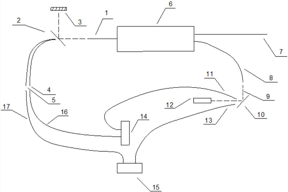
[0038] Such as figure 1 As shown, in order to make the purpose, technical solution and advantages of the present invention more clear, the present invention will be further described in detail below in conjunction with the accompanying drawings and embodiments.

[0039] The implementation mode of the high-power fiber laser safety monitoring method in the embodiment of the present invention is as follows:

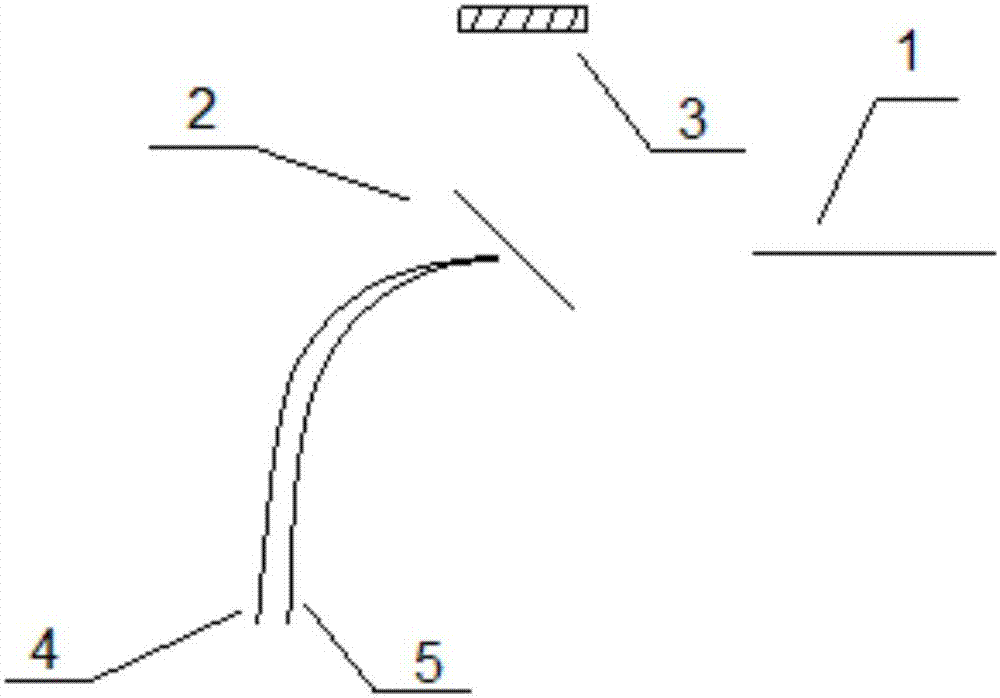
[0040] First build the monitoring channel at the output end, such as figure 1 As shown, 1 is the output fiber, 2 is the high reflective mirror with high reflection rate to the laser (99.5%-99.95%), 3 is the power meter, the output laser is output from 1, and most of it enters the power meter through the high reflective mirror. Only a very small part of the light is transmitted through 2 and enters the coreless optical fibers 4 and 5 (ie, the monitoring channel). Coreless fibers 4 and 5 need to be as close as possible to receive enough signal light.

[0041] The next step ...


PUM


Abstract

A high-power fiber laser safety monitoring method comprises the following steps of: S1, establishing a monitoring channel for monitoring an output terminal and the light returning terminal of a forward combiner (usually the suspending arm of the combiner); S2, establishing a monitoring system that comprises a red light indicating part, a spectrum monitoring part, a waveform monitoring part, a thermal imager monitoring part and a power meter monitoring part; and S3 establishing a monitoring index for establishing the indexes of a fiber laser in normal operation, the indexes including a static index and a dynamic index.

Description

technical field [0001] The invention relates to the technical field of fiber laser monitoring, in particular to a high-power fiber laser safety monitoring method and device. Background technique [0002] There are two main methods for safety monitoring of the working status of high-power fiber lasers, one is to monitor the power abnormality through a power meter, and the other is to observe the surface temperature of the fiber and its components through a thermal imager. Or combine the two methods to judge whether there is any abnormality in the working state of the fiber laser. However, in many cases, the active optical fiber is buried in a water-cooled tank and is surrounded by thermally conductive silicone grease. In addition, optical fiber devices such as gratings, beam combiners, or CPS have packaging structures. These factors lead to their internal The temperature is difficult to observe, and the abnormality of the surface temperature cannot be predicted in advance. A...

Claims


Application Information

Patent Timeline
Patent Type & Authority Applications(China)
IPC IPC(8): G01M11/02
CPCG01M11/00
Inventor 李进延贺兴龙廖雷邢颍滨陈益沙张芳芳李海清戴能利彭景刚杨旅云刘茵紫
Owner EZHOU INST OF IND TECH HUAZHONG UNIV OF SCI & TECH
Why Eureka
Try Eureka