High-voltage switchgear monitoring system

A high-voltage switchgear and monitoring system technology, applied in the field of switchgear, can solve the problems of inability to observe the operating state of the switchgear intuitively, the monitoring device cannot achieve effective detection, and cannot be effectively monitored, so as to reduce losses.

Inactive Publication Date: 2017-09-29
合肥易美特建材有限公司
View PDF1 Cites 13 Cited by
  • Summary
  • Abstract
  • Description
  • Claims
  • Application Information

AI Technical Summary

Problems solved by technology

[0004] Due to its high voltage level, the monitoring of high-voltage switchgear has always been a problem that is difficult to solve in the industry. Many monitoring devices cannot achieve effective detection results.
[0005] In

Method used


Image

  • High-voltage switchgear monitoring system
  • High-voltage switchgear monitoring system

Examples


Embodiment 1

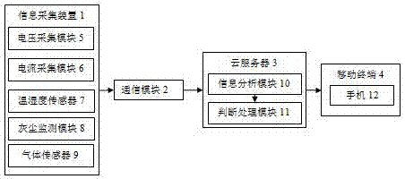
[0030] see figure 1 , this embodiment relates to a high-voltage switchgear monitoring system, including an information collection device 1, a communication module 2, a cloud server 3 and a mobile terminal 4;

[0031] The information collection device 1 is used to monitor the voltage, current, insulation, temperature and humidity, and the action of the circuit breaker in the high-voltage switchgear. The information collection device includes a voltage collection module 5, a current collection module 6, a temperature and humidity sensor 7. Dust monitoring module 8 and gas sensor 9;

[0032] The communication module 2 is used to transfer the information collected by the information collection device 1 to the cloud server 3;

[0033] The cloud server 3 is used to analyze and process the information collected by the information collection device to obtain a result and transmit it to the mobile terminal 4;

[0034] The mobile terminal 4 is used for staff to receive information tra...

Embodiment 2

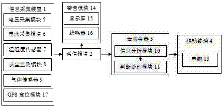
[0043] see figure 2 , this embodiment relates to a high-voltage switchgear monitoring system, including an information collection device 1, a communication module 2, a cloud server 3 and a mobile terminal 4;

[0044] The information collection device 1 is used to monitor the voltage, current, insulation, temperature and humidity, and the action of the circuit breaker in the high-voltage switchgear. The information collection device includes a voltage collection module 5, a current collection module 6, a temperature and humidity sensor 7. Dust monitoring module 8 and gas sensor 9;

[0045] The communication module 2 is used to transfer the information collected by the information collection device 1 to the cloud server 3;

[0046] The cloud server 3 is used to analyze and process the information collected by the information collection device to obtain a result and transmit it to the mobile terminal 4;

[0047] The mobile terminal 4 is used for staff to receive information tr...


PUM


Abstract

The invention discloses a high-voltage switchgear monitoring system and relates to the technical field of switchgears. The high-voltage switchgear monitoring system comprises an information acquisition apparatus, a communication module, a cloud server and a mobile terminal, wherein the information acquisition apparatus monitors the voltage, current, insulation, humiture and breaker action in a high-voltage switchgear, and comprises a voltage acquisition module, a current acquisition module, a humiture sensor, a dust monitoring module and a gas sensor, the communication module transmits the information acquired by the information acquisition apparatus to the cloud server, the cloud server analyzes and processes the information acquired by the information acquisition apparatus to obtain result and sends the result to a mobile terminal, and the mobile terminal allows workers to receive information sent by the cloud server. The high-voltage switchgear monitoring system can realize real-time remote monitoring of a high-voltage switchgear. Effective monitoring can be achieved by monitoring a plurality of parameters in the high-voltage switchgear, and the operation state of the high-voltage switchgear can be known accurately.

Description

technical field [0001] The invention relates to the technical field of switch cabinets, in particular to a monitoring system for high-voltage switch cabinets. Background technique [0002] The switch cabinet is a kind of electrical equipment. The outside line of the switch cabinet first enters the main control switch in the cabinet, and then enters the sub-control switch. Each branch is set according to its needs. Such as instruments, automatic controls, motor magnetic switches, various AC contactors, etc., some also have high-voltage room and low-voltage room switch cabinets, high-voltage busbars, such as power plants, etc. load shedding. [0003] High-voltage switchgear refers to the role of on-off, control or protection in power system power generation, transmission, distribution, power conversion and consumption. High-voltage switchgear is used as electrical products with a voltage level of 3.6kV ~ 550kV, and high-voltage isolating switches And grounding switch, high-v...

Claims


Application Information

Patent Timeline
IPC IPC(8): H02J13/00
CPCH02J13/00H02J13/00001Y02E60/00Y04S40/126
Inventor 朱明静
Owner 合肥易美特建材有限公司
Why Eureka
Try Eureka