Current mode RM or non- xor unit based on FinFET transistor

A current mode and transistor technology, applied in the field of RM logic or non-exclusive OR unit, can solve the problems of large circuit area, delay and power consumption delay product, power consumption increase, etc., and achieve power consumption and power consumption delay The effect of small time product, reduced area, and reduced delay

Active Publication Date: 2017-09-29
NINGBO UNIV
View PDF6 Cites 0 Cited by
  • Summary
  • Abstract
  • Description
  • Claims
  • Application Information

AI Technical Summary

Problems solved by technology

The RM logic does not avoid the series connection of CMOS transistors in the pull-down network, resulting in a three-layer logic. The series connection of CMOS transistors will cause the stack height from the power supply to the ground to be too long. In order to make the circuit work normally, it is necessary to increase the working power of the circuit accordingly. The power consumption will increase accordingly, and the number of transistors used in the circuit will be larger at the same time, resulting in a larger circuit area, delay and power consumption delay product

Method used


Image

  • Current mode RM or non- xor unit based on FinFET transistor
  • Current mode RM or non- xor unit based on FinFET transistor
  • Current mode RM or non- xor unit based on FinFET transistor

Examples


Embodiment 1

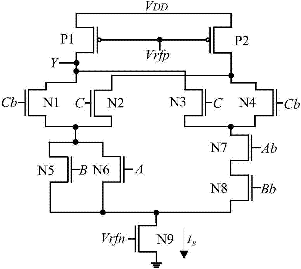
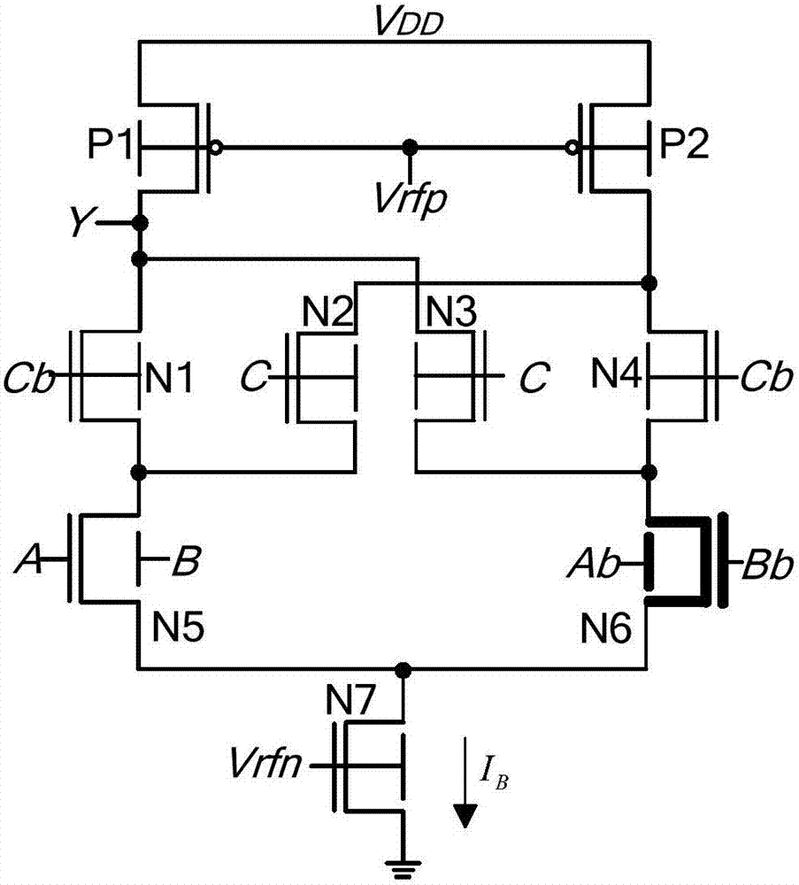
[0015] Embodiment one: if figure 2As shown, an RM or non-exclusive OR unit based on FinFET transistors includes a first P-type FinFET transistor P1, a second P-type FinFET transistor P2, a first N-type FinFET transistor N1, a second N-type FinFET transistor N2, The third N-type FinFET tube N3, the fourth N-type FinFET tube N4, the fifth N-type FinFET tube N5, the sixth N-type FinFET tube N6 and the seventh N-type FinFET tube N7, the first P-type FinFET tube P1 and the second N-type FinFET tube The P-type FinFET tube P2 is a low-threshold P-type FinFET tube, the first N-type FinFET tube N1, the second N-type FinFET tube N2, the third N-type FinFET tube N3, the fourth N-type FinFET tube N4, and the fifth N-type tube The FinFET tube N5 and the seventh N-type FinFET tube N7 are low-threshold N-type FinFET tubes, and the sixth N-type FinFET tube N6 is a high-threshold N-type FinFET tube; the source of the first P-type FinFET tube P1 and the second P-type FinFET tube The source of...

Embodiment 2

[0018] Embodiment two: if figure 2 As shown, an RM or non-exclusive OR unit based on FinFET transistors includes a first P-type FinFET transistor P1, a second P-type FinFET transistor P2, a first N-type FinFET transistor N1, a second N-type FinFET transistor N2, The third N-type FinFET tube N3, the fourth N-type FinFET tube N4, the fifth N-type FinFET tube N5, the sixth N-type FinFET tube N6 and the seventh N-type FinFET tube N7, the first P-type FinFET tube P1 and the second N-type FinFET tube The P-type FinFET tube P2 is a low-threshold P-type FinFET tube, the first N-type FinFET tube N1, the second N-type FinFET tube N2, the third N-type FinFET tube N3, the fourth N-type FinFET tube N4, and the fifth N-type tube The FinFET tube N5 and the seventh N-type FinFET tube N7 are low-threshold N-type FinFET tubes, and the sixth N-type FinFET tube N6 is a high-threshold N-type FinFET tube; the source of the first P-type FinFET tube P1 and the second P-type FinFET tube The source o...

Embodiment 3

[0022] Embodiment three: as figure 2 As shown, an RM or non-exclusive OR unit based on FinFET transistors includes a first P-type FinFET transistor P1, a second P-type FinFET transistor P2, a first N-type FinFET transistor N1, a second N-type FinFET transistor N2, The third N-type FinFET tube N3, the fourth N-type FinFET tube N4, the fifth N-type FinFET tube N5, the sixth N-type FinFET tube N6 and the seventh N-type FinFET tube N7, the first P-type FinFET tube P1 and the second N-type FinFET tube The P-type FinFET tube P2 is a low-threshold P-type FinFET tube, the first N-type FinFET tube N1, the second N-type FinFET tube N2, the third N-type FinFET tube N3, the fourth N-type FinFET tube N4, and the fifth N-type tube The FinFET tube N5 and the seventh N-type FinFET tube N7 are low-threshold N-type FinFET tubes, and the sixth N-type FinFET tube N6 is a high-threshold N-type FinFET tube; the source of the first P-type FinFET tube P1 and the second P-type FinFET tube The source...


PUM


Abstract

The invention discloses a current mode RM or non- xor unit based on a FinFET transistor. The current mode RM or non- xor unit comprises a first P type FinFET tube, a second P type FinFET tube, a first N type FinFET tube, a second N type FinFET tube, a third N type FinFET tube, a fourth N type FinFET tube, a fifth N type FinFET tube, a sixth N type FinFET tube and a seventh N type FinFET tube, wherein the first P type FinFET tube and the second P type FinFET tube are low-threshold P type FinFET tubes, the first N type FinFET tube, the second N type FinFET tube, the third N type FinFET tube, the fourth N type FinFET tube, the fifth N type FinFET tube, the sixth N type FinFET tube and the seventh N type FinFET tube are high-threshold N type FinFET tubes. The current mode RM or non- xor unit has the advantages that the circuit area, the delay, the power consumption and the power delay product are smaller on the basis of a current logic function.

Description

technical field [0001] The invention relates to an RM logic OR non-exclusive OR unit, in particular to a current mode RM OR non-exclusive OR unit based on a FinFET transistor. Background technique [0002] The basic gate circuit is the most basic logic unit in the digital circuit, and the XOR and XOR gate circuits are an indispensable part of the basic logic circuit. Current-mode logic circuits have the characteristics of high operating frequency, low power consumption, and strong anti-interference ability. However, traditional CMOS current-mode logic still faces the problems of large number of transistors, high power consumption, and complex design. With the continuous advancement of VLSI technology, the operating speed and power consumption requirements of digital systems continue to increase, and the performance requirements for basic logic units are also more stringent, requiring that basic logic units should have lower power consumption and smaller delay. [0003] When...

Claims


Application Information

Patent Timeline
Patent Type & Authority Applications(China)
IPC IPC(8): H03K19/20
CPCH03K19/20
Inventor 胡建平熊阳杨廷锋汪佳峰
Owner NINGBO UNIV
Why Eureka
Try Eureka