Sound leakage suppression structure for bone-conduction headphone

A bone conduction earphone and bone conduction speaker technology, which is applied to bone conduction transducer hearing equipment, sensors, sensor parts, etc., can solve the problems of shell vibration, sound leakage of bone conduction earphones, limited buffering effect of connecting column, etc. The effect of reducing sound leakage and increasing the vibration space

Pending Publication Date: 2017-09-29
SHENZHEN VIDONN INFORMATION TECH CO LTD
View PDF3 Cites 7 Cited by
  • Summary
  • Abstract
  • Description
  • Claims
  • Application Information

AI Technical Summary

Problems solved by technology

like figure 1 As shown, in the prior art, the bone conduction speaker (1) is directly connected to the earphone housing (3), causing the housing (3) to vibrate and produce sound without any treatment to suppress sound leakage; another prior art such as figure 2 As shown, the sound leakage problem is solved by vertically stacking the bone conduction speaker (1), the connecting column (5), and the earphone shell (3), but the buffering effect of the connecting column (5) is limited
Therefore, the currently disclosed technology has not yet found a suitable way to better solve the problem of bone conduction earphone sound leakage.

Method used


Image

  • Sound leakage suppression structure for bone-conduction headphone
  • Sound leakage suppression structure for bone-conduction headphone
  • Sound leakage suppression structure for bone-conduction headphone

Examples


Embodiment 1

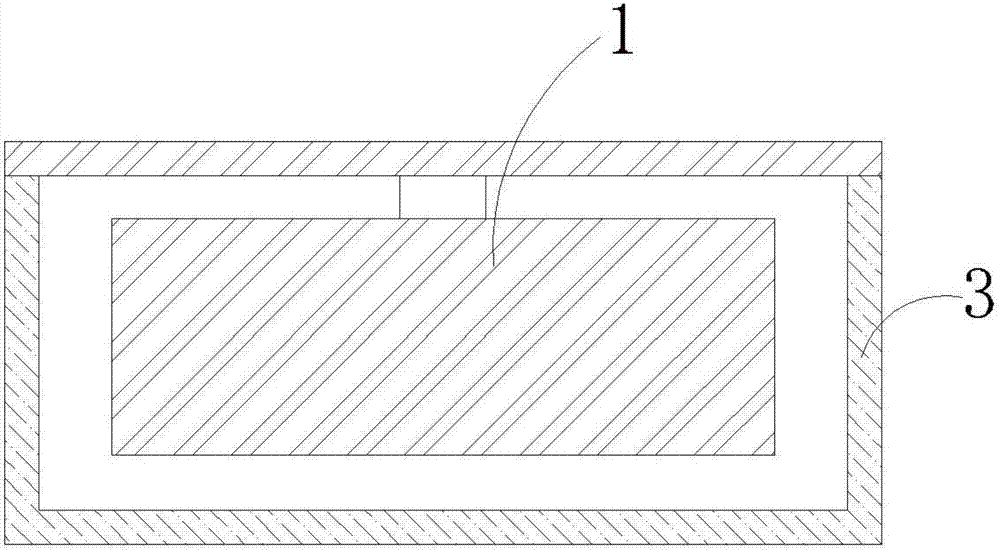
[0025] like image 3 As shown, the present invention provides a bone conduction earphone suppressing sound leakage structure, comprising a bone conduction speaker 1, a vibration damping layer 2 and a housing 3, the bone conduction speaker 1 is connected to the vibration damping layer 2, and the vibration damping layer 2 It is mated and connected with the shell 3; the bone conduction speaker 1 is not in direct contact with the shell 3, and is separated by the vibration-damping layer 2. The bone conduction loudspeaker 1 generates mechanical vibration during operation, which is buffered by the vibration-damping layer 2 , and only a very small part of the energy is transmitted to the casing 3 .

[0026] The vibration-damping layer 2 is a vibration-damping layer of elastic material.

[0027] The damping layer 2 is one or more of rubber, TPR, TPX, TPV, TPO, TPU, TPEE, TPE, SEBS, SBS, SIS, TPSIV, PVC, PU, ​​silica gel, metal foil, and paper.

[0028] The main body of the damping la...

Embodiment 2

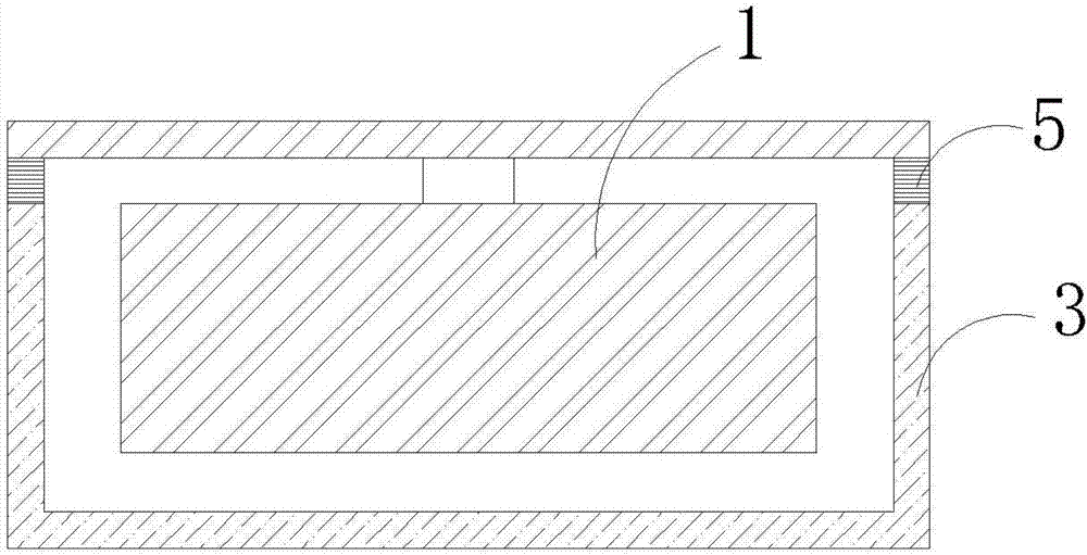
[0034] like Figure 4 As shown, the present invention provides a bone conduction earphone suppressing sound leakage structure, comprising a bone conduction speaker 1, a vibration damping layer 2 and a housing 3, the bone conduction speaker 1 is connected to the vibration damping layer 2, and the vibration damping layer 2 It is mated and connected with the shell 3; the bone conduction speaker 1 is not in direct contact with the shell 3, and is separated by the vibration-damping layer 2. The bone conduction loudspeaker 1 generates mechanical vibration during operation, which is buffered by the vibration-damping layer 2 , and only a very small part of the energy is transmitted to the casing 3 .

[0035] The vibration-damping layer 2 is a vibration-damping layer of elastic material.

[0036] The damping layer 2 is one or more of rubber, TPR, TPX, TPV, TPO, TPU, TPEE, TPE, SEBS, SBS, SIS, TPSIV, PVC, PU, ​​silica gel, metal foil, and paper.

[0037] The main body of the damping l...

Embodiment 3

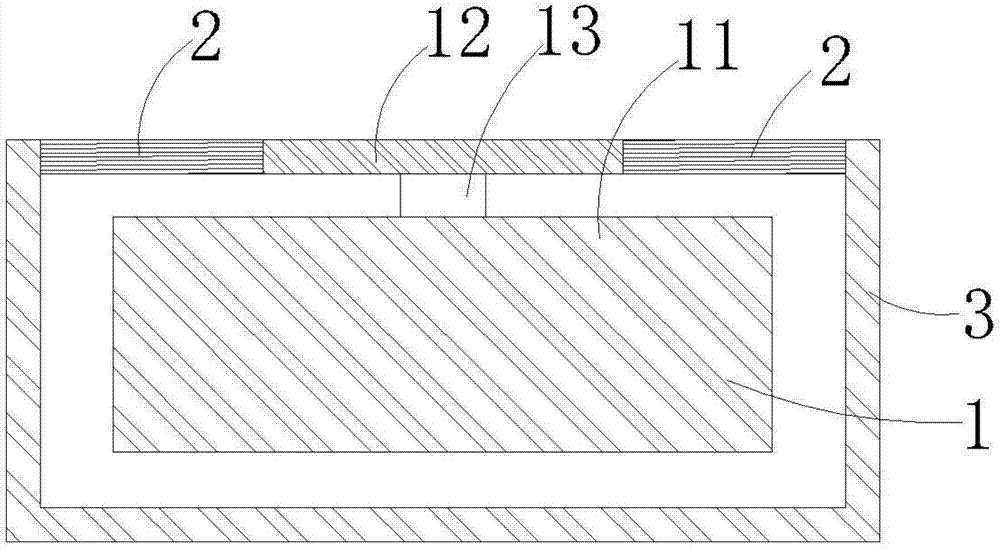
[0043] like Figure 5 As shown, the present invention provides a bone conduction earphone suppressing sound leakage structure, comprising a bone conduction speaker 1, a vibration damping layer 2 and a housing 3, the bone conduction speaker 1 is connected to the vibration damping layer 2, and the vibration damping layer 2 It is mated and connected with the shell 3; the bone conduction speaker 1 is not in direct contact with the shell 3, and is separated by the vibration-damping layer 2. The bone conduction loudspeaker 1 generates mechanical vibration during operation, which is buffered by the vibration-damping layer 2 , and only a very small part of the energy is transmitted to the casing 3 .

[0044] The vibration-damping layer 2 is a vibration-damping layer of elastic material.

[0045] The damping layer 2 is one or more of rubber, TPR, TPX, TPV, TPO, TPU, TPEE, TPE, SEBS, SBS, SIS, TPSIV, PVC, PU, ​​silica gel, metal foil, and paper.

[0046] The main body of the damping l...


PUM


Abstract

The invention discloses a sound leakage suppression structure for a bone-conduction headphone, which belongs to the technical field of bone-conduction headphones. The sound leakage suppression structure for the bone-conduction headphone comprises a bone conduction loudspeaker, a vibration attenuation layer and a shell, wherein the bone conduction loudspeaker is connected with the vibration attenuation layer; the vibration attenuation layer is in matched connection with the shell; and the bone conduction loudspeaker is not directly contacted with the shell, and the two are separated through the vibration attenuation layer. According to the structure of the invention, the vibration space of the bone conduction loudspeaker can be increased, energy generated by vibration can be better absorbed, and energy transmission to the shell is avoided; and through the vibration attenuation layer, the mechanical vibration generated by the bone conduction loudspeaker can be absorbed, and leaked sounds generated when the mechanical vibration energy is transmitted to the shell of the headphone can be reduced.

Description

technical field [0001] The invention belongs to the technical field of bone conduction earphones, in particular to a structure for suppressing sound leakage of bone conduction earphones. Background technique [0002] Bone conduction earphones convert electrical signals into mechanical vibrations, and the mechanical vibrations are transmitted to the human ear through human tissue to produce hearing; compared with the classic sound conduction method of generating sound waves through the diaphragm, bone conduction saves many steps of sound wave transmission and can Clear sound reproduction can be achieved in noisy environments, and sound waves will not affect others due to diffusion in the air. [0003] At present, the sound leakage problem of bone conduction earphones has not been well solved. There are two main sources of sound leakage. On the one hand, bone conduction speakers will vibrate when they work, which will drive the surrounding air to emit sound; on the other hand,...

Claims


Application Information

Patent Timeline
Patent Type & Authority Applications(China)
IPC IPC(8): H04R1/28
CPCH04R1/288H04R2460/13
Inventor 黄体钦杜志国王猛
Owner SHENZHEN VIDONN INFORMATION TECH CO LTD
Why Eureka
Try Eureka