
Cap Unit For Puncture Repair

A technology for repairing air leaks and compressing air, which is applied in vehicle maintenance/repair, applications, household appliances, etc. It can solve the problems of passenger discomfort, abnormal noise, etc., and achieve the effect of ensuring quiet performance

Inactive Publication Date: 2017-10-03
SUMITOMO RUBBER IND LTD
View PDF2 Cites 0 Cited by
  • Summary
  • Abstract
  • Description
  • Claims
  • Application Information

AI Technical Summary

Problems solved by technology

However, during the storage process, the ball valve moves freely in the first flow path due to the vibration of the vehicle running, so there is a problem of generating abnormal noise and causing discomfort to the occupants

Method used


Image

  • Cap Unit For Puncture Repair
  • Cap Unit For Puncture Repair
  • Cap Unit For Puncture Repair

Examples


Embodiment

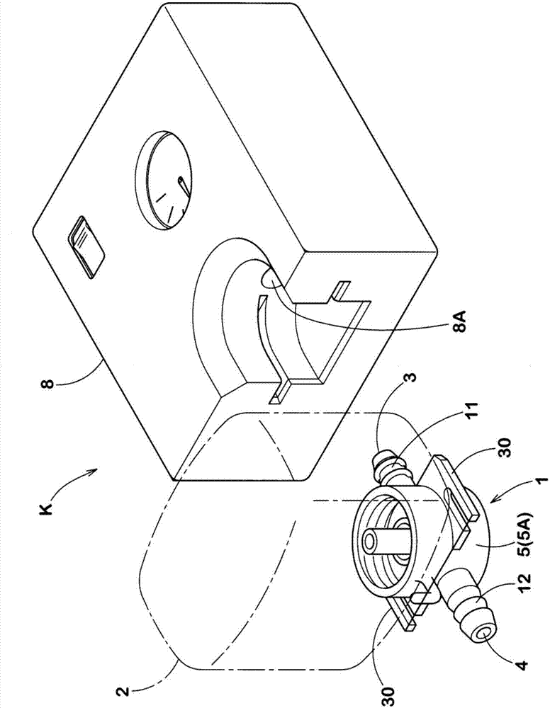
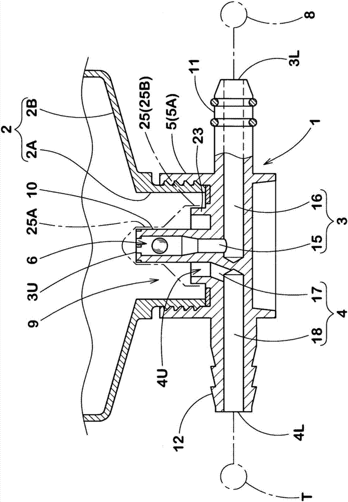
[0046] In order to confirm the effect of the present invention, a trial production was carried out according to the specifications in Table 1. figure 2 Cover unit of the configuration shown. In addition, the injection and boosting time of each cover unit, whether there is a reverse flow of air leakage repair fluid, and whether there is abnormal noise from the ball valve are tested. The specific gravity, rebound elastic modulus, and low-temperature embrittlement temperature of the ball valve are changed by changing the material of the rubber elastic body.

[0047] (1) Injection boost time:

[0048] The time required to inject 400 cc of blow-by repair fluid into a tire (195 / 65R15) using a shared compressor and raise the internal pressure of the tire pressure gauge from 0 to 250 kPa was measured. The ambient temperature is -30°C.

[0049] (2) Whether there is backflow of air leakage repair fluid:

[0050] The cover unit was taken out after the blow-by repair fluid injection ...


PUM


Abstract

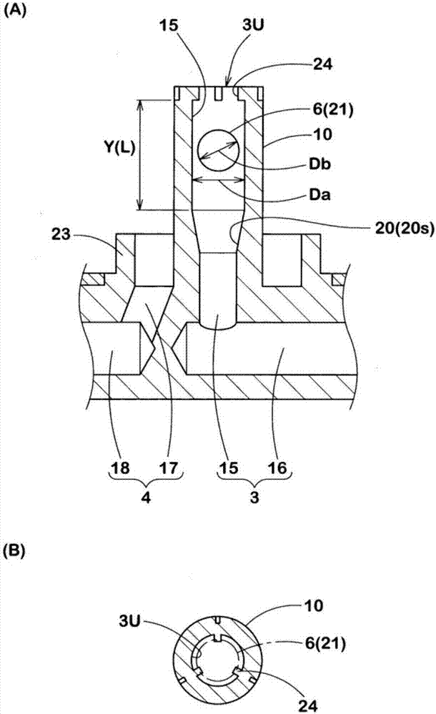
[Problems] To suppress the occurrence of abnormal noise from a ball valve due to vibrations during the vehicle is traveling, while employing a simple structure. [Means for solving the problems] A check valve 6 for preventing a backflow of a puncture repair liquid from a bottle container 2 is disposed in a first flow path 3 for taking compressed air from a compressor 8 into a bottle container 2. The check valve is formed by a ball valve 21 disposed in a valve housing zone Y which is located in a vertical passage part 15 of the first flow path 3 and between an upper opening 3U and a valve seat portion 20. The ball valve 21 is formed from a rubber elastic body having a specific gravity of 1.1 or more, and a rebound resilience of 15% or less.

Description

technical field [0001] The present invention relates to a leak repair cap unit for emergency repair of the leak by sequentially injecting a leak repair liquid and compressed air into the leaked tire. Background technique [0002] For example, Patent Document 1 below proposes a cover unit for air leak repair. like Figure 4 As shown, the cap unit is equipped with a check valve b for preventing the backflow of the air leakage repair fluid in the first flow path a that takes compressed air from the compressor into the bottle container. The check valve b of this proposal has: a metal ball valve b1 arranged in the valve accommodation area c in the first flow path a; a rubber valve seat b2 provided at the lower end of the valve accommodation area c; The force spring b3 on the valve seat b2, and the structure is complicated, which leads to an increase in cost. [0003] On the other hand, Patent Document 2 below discloses a check valve having a simple structure in which a metal ba...

Claims


Application Information

Patent Timeline
Patent Type & Authority Applications(China)
IPC IPC(8): B29C73/02B29L30/00
CPCB29C73/025B29L2030/00B29C73/166B60S5/043F16K15/044F16K15/048
Inventor 永田幸则
Owner SUMITOMO RUBBER IND LTD
Learn More