
A brake control device and control method for electric vehicles

A brake control, electric vehicle technology, applied in electric vehicles, control devices, transmission parts, etc., can solve the slip rate control effect and the deterioration of driving comfort, no transmission system characteristic compensation, torque oscillation at the wheel and other problems, to achieve the effect of improving the braking control effect and improving the driving comfort

Active Publication Date: 2018-11-30
TSINGHUA UNIV
View PDF5 Cites 0 Cited by
  • Summary
  • Abstract
  • Description
  • Claims
  • Application Information

AI Technical Summary

Problems solved by technology

And when the vehicle changes from driving to braking, the contact surface of the gears in the drive train is reversed, and the drive train passing through the backlash will cause an impact when the gears re-contact, resulting in the oscillation of the torque at the wheel
When the motor feedback braking torque is dynamically adjusted at a higher frequency, especially in the anti-lock braking process using the motor, the negative influence of the elasticity and backlash of the drive train is intensified, resulting in slip ratio control effect and driving Ride comfort further deteriorates
[0004] In the prior art, a powertrain characteristic compensation method is proposed for the driving process of internal combustion engine vehicles. However, this compensation method only involves compensating the powertrain characteristics during the driving process of traditional internal combustion engine vehicles, and does not target electric vehicles, especially electric vehicles. Compensation of drive train characteristics during braking
Due to the faster motor torque response of electric vehicles, and there may be coupling between regenerative braking force and hydraulic braking force during braking, the compensation control of the drive train characteristics during motor regenerative braking is more complicated

Method used


Image

  • A brake control device and control method for electric vehicles
  • A brake control device and control method for electric vehicles
  • A brake control device and control method for electric vehicles

Examples


Embodiment Construction

[0023] The present invention will be described in detail below in conjunction with the accompanying drawings. However, it should be understood that the accompanying drawings are provided only for better understanding of the present invention, and they should not be construed as limiting the present invention.

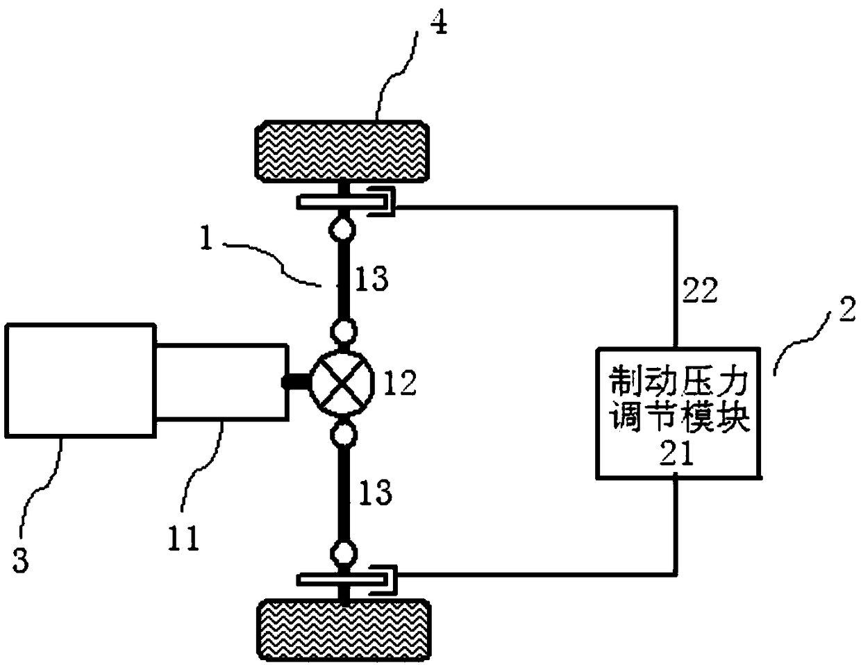
[0024] Such as figure 1 As shown, the present invention includes a transmission system 1 and a hydraulic control system 2 with the driving and braking system of an electric vehicle, wherein the transmission system 1 comprises a gearbox 11, a differential 12 and two axle shafts 13, and the hydraulic control system 2 comprises a braking system. The dynamic pressure adjustment module 21 and the hydraulic brake pipeline 22, the motor 3 of the electric vehicle are respectively connected to a wheel 4 of the electric vehicle through the gearbox 11 and the differential 12 through the two half shafts 13, and the brake pressure adjustment module 21 is respectively connected to a ...


PUM


Abstract

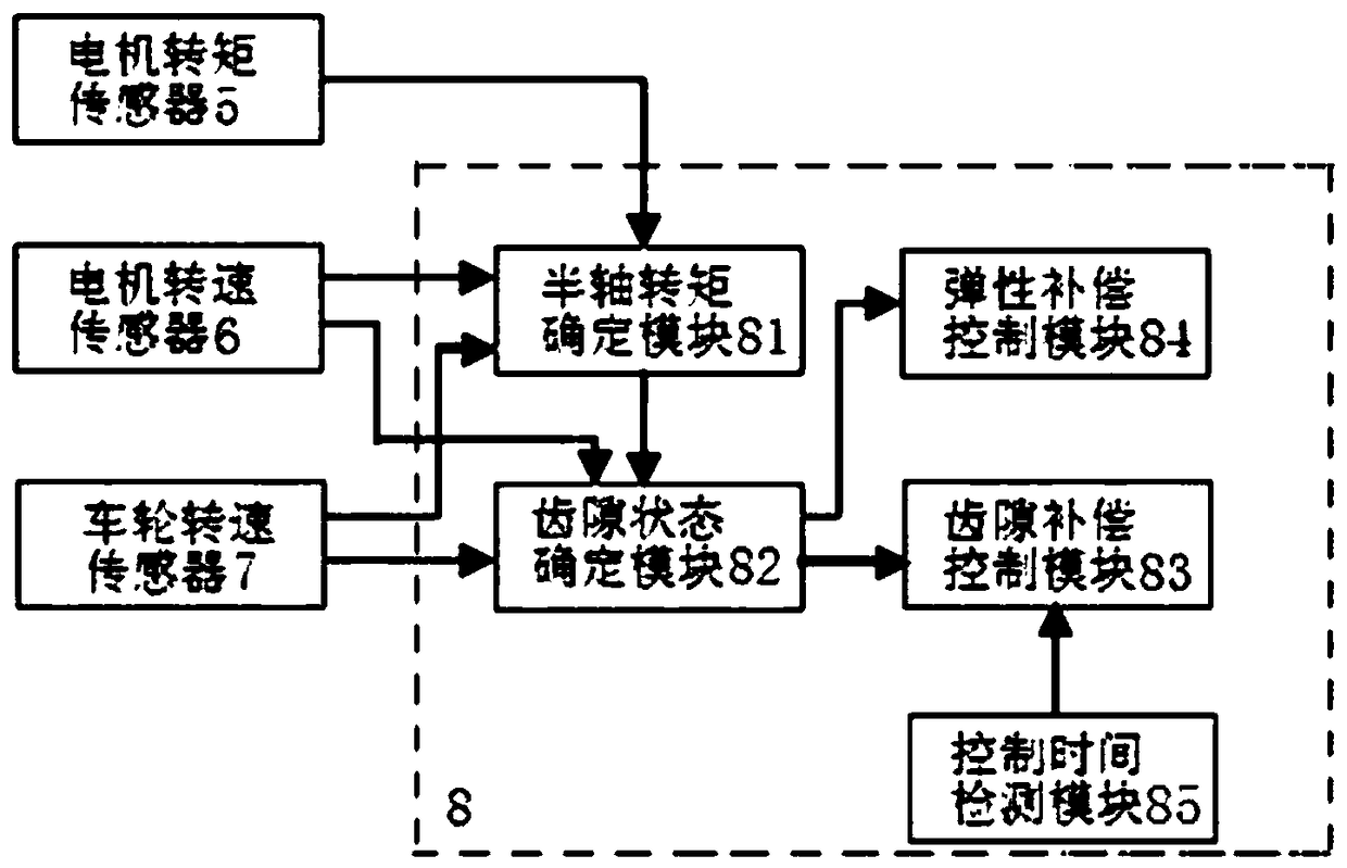
The invention relates to a brake control device and control method for electric vehicles, which compensates the characteristics of the transmission system by adjusting the feedback braking force of the motor and the hydraulic braking force of the hydraulic control system, and is characterized in that it includes a motor torque sensor, A motor speed sensor, a wheel speed sensor, and a vehicle-mounted braking control system, wherein the vehicle-mounted braking control system includes a half-axis torque determination module, a backlash state determination module, a backlash compensation control module, an elastic compensation control module, and a control time detection module; determine the backlash state through the backlash state determination module, and perform backlash compensation control or elasticity compensation control on the transmission system through the backlash compensation control module or the elastic compensation control module according to the backlash state at the meshing position of the gears in the transmission system, The invention can reduce the risk of impact and oscillation of the feedback braking torque at the corresponding wheel due to the backlash and elasticity of the transmission system, and can be widely used in the technical field of electric vehicles.

Description

technical field [0001] The invention relates to a braking control device and a control method for an electric vehicle, belonging to the technical field of electric vehicles. Background technique [0002] In electric vehicles such as pure electric vehicles, hybrid electric vehicles and fuel cell electric vehicles, part of the kinetic energy of the vehicle can be converted into electric energy through the motor feedback braking function to improve the energy economy of the vehicle, and the motor torque control can also be used to quickly Accurate characteristics dynamically adjust electric vehicles at a higher frequency to achieve improved vehicle anti-lock braking effects. In the prior art, when the regenerative braking is performed by the motor, the default transmission system is rigid, and the control of the regenerative braking torque of the motor is open-loop. , to achieve the target slip ratio at the corresponding wheel by controlling the regenerative braking torque of ...

Claims


Application Information

Patent Timeline
Patent Type & Authority Patents(China)
IPC IPC(8): B60L7/26F16H57/12
CPCB60L7/26F16H57/12F16H2057/123B60L2240/421B60L2240/423B60L2240/461Y02T10/64Y02T10/72B60L15/2009B60L2240/12
Inventor 张俊智张仲石马瑞海
Owner TSINGHUA UNIV
Learn More