High-thrust cable winding displacement equipment capable of delayed automatic reverse and winding displacement method thereof
A technology of automatic reversing and high thrust, which is applied in the direction of thin material handling, conveying filamentous materials, transportation and packaging, etc. It can solve the problems of uneven wiring, etc., and achieve high precision, large thrust, and precise automatic wiring. Effect
- Summary
- Abstract
- Description
- Claims
- Application Information
AI Technical Summary
Problems solved by technology
Method used
Image
Examples
specific Embodiment approach 1
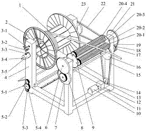
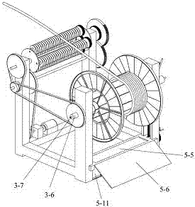
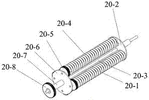
[0017] Specific implementation mode one: combine Figure 1~Figure 5This embodiment will be described. This implementation mode provides a specific implementation scheme of a large-thrust cable arrangement device with time-delayed automatic reversing. The high-thrust cable routing equipment with time-delay automatic reversing cable routing equipment consists of a cable 1, a reel 2, a clamping and positioning device 3, a frame 4, a lifting device 5, an incomplete gear 6, and a gear 7 , Incomplete gear two 8, transmission shaft one 9, motor 10, connecting shaft one 11, speed changer 12, connecting shaft two 13, pulley one 14, belt one 15, pulley two 16, pulley three 17, pulley four 18, belt two 19, cable arrangement 20, belt pulley five 21, belt three 22 and belt pulley six 23 form. One end of the cable 1 is wound on the reel 2 through the limit hole on the reel 2, and the other end is placed in the thread groove of the cable arrangement 20; the reel 2 is clamped and supported ...
specific Embodiment approach 2
[0020] Specific implementation mode two: combination figure 1 , Figure 4 with Figure 5 This specific embodiment will be described. This embodiment provides a specific implementation scheme of a cable routing method for a large-thrust cable routing device with time-delayed automatic reversing. The cable routing method of a large-thrust cable routing device with time-delayed automatic reversing is as follows.
[0021] The cable movement mode is: the motor is energized to work, and the power is transmitted to the transmission shaft one 9. The transmission shaft one 9 has two power outputs, one is that the transmission shaft one 9 drives the pulley four 18 to rotate, and the belt three 22 drives the belt The wheel 6 23 rotates, and transmits the power to the support sleeve 2 3-6 of the clamping and positioning device, and then drives the friction cylinder 3-14 to rotate, and relies on the friction force between the friction cylinder 3-14 and the reel 2 to drive the scroll 2 t...
specific Embodiment approach 3
[0022] Specific implementation mode three: combination figure 2 with Figure 5 This specific embodiment will be described. This embodiment provides a specific implementation of a drum clamping and positioning method. The method for clamping and positioning a reel is as follows.
[0023] Reel clamping positioning realization method: the reel 2 rolls along the inclined plane 5-6 into the arc groove of the lifting plate 5-5, the center axis of the arc groove and the centering axis of the clamping device are located on the same plane, realizing the reel 2 lead Automatic centering in vertical direction. Shaking the hand rocker 5-1 drives gear five 5-2 to rotate, gear seven 5-4 meshes with gear five 5-2, gear six 5-3 meshes with gear seven 5-4, and gear five 5-2 has the smallest diameter , the diameter of gear seven 5-4 is the largest, and its purpose is to increase the output torque. The rotation of gear six 5-3 drives the rotation of bevel gear five 5-15 on the same shaft se...
PUM
 Abstract
Description
Claims
Application Information
 - R&D
- Intellectual Property
- Life Sciences
- Materials
- Tech Scout
- Unparalleled Data Quality
- Higher Quality Content
- 60% Fewer Hallucinations
Browse by: Latest US Patents, China's latest patents, Technical Efficacy Thesaurus, Application Domain, Technology Topic, Popular Technical Reports.
© 2025 PatSnap. All rights reserved.Legal|Privacy policy|Modern Slavery Act Transparency Statement|Sitemap|About US| Contact US: help@patsnap.com


