Shock exciting and tamping device and parameter determination method of hydraulic tamping machine
A technology of tamping machine and vibrating device, which is applied in the direction of road, track, ballast layer, etc., can solve the problems that anti-phase vibration and asynchronous clamping cannot be realized, and the vibration amplitude cannot be adjusted.
- Summary
- Abstract
- Description
- Claims
- Application Information
AI Technical Summary
Problems solved by technology
Method used
Image
Examples
Embodiment Construction
[0065] Below in conjunction with accompanying drawing, the present invention will be further described:
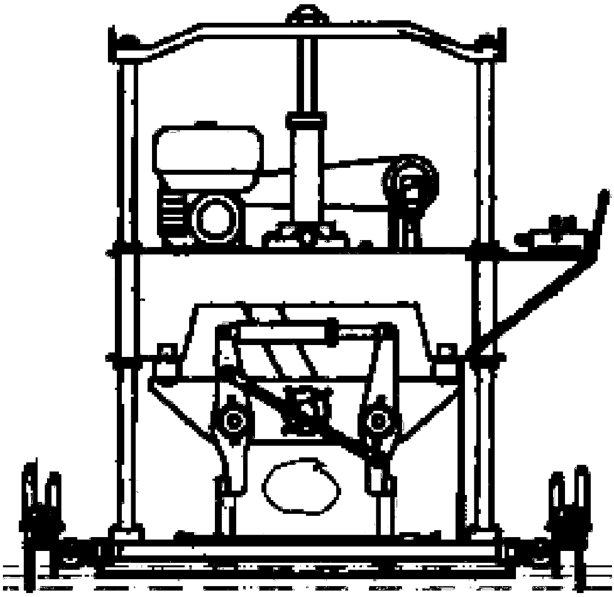
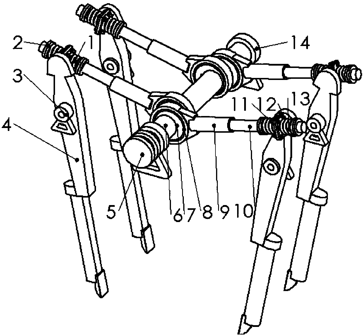
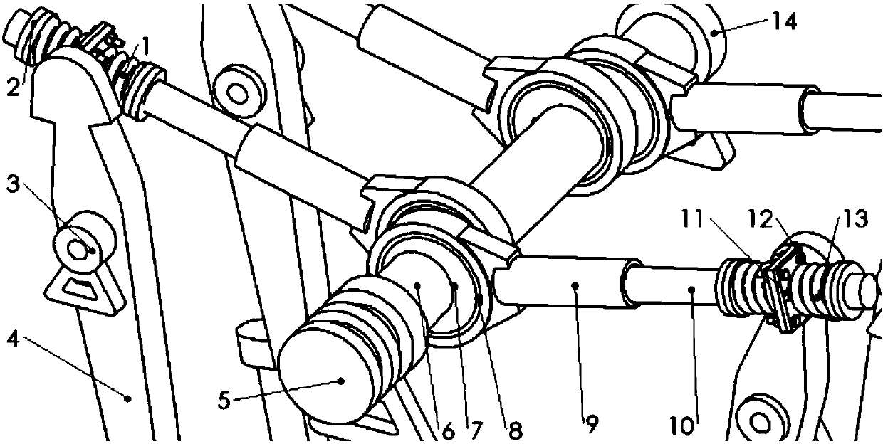
[0066] The invention provides a new type of vibration excitation and tamping device for a small hydraulic tamping machine, see Figure 1-Figure 7 . figure 1 It is a schematic diagram of a traditional hydraulic tamping machine, the power unit and frame used in the implementation example of the present invention and figure 1 The traditional hydraulic tamping machine is the same, and the present invention is used to replace figure 1 the whole vibration part.
[0067] The design parameter of the example of the present invention is: λ=0.75mm, ω=293.215rad / s, z 0 = 4, m 石 =2.326kg, J is 0.565kg·m 2 , G=130.124N, p=0.119m, l=0.245m, h=0.490m.
[0068] Bring the above data into the equations (11) to (13), calculate the eccentricity r=11mm, and the spring stiffness k=100226.037N / m.
[0069] The internal combustion engine transmits power to the pulley 5 through the belt, an...
PUM
 Abstract
Description
Claims
Application Information
 - R&D
- Intellectual Property
- Life Sciences
- Materials
- Tech Scout
- Unparalleled Data Quality
- Higher Quality Content
- 60% Fewer Hallucinations
Browse by: Latest US Patents, China's latest patents, Technical Efficacy Thesaurus, Application Domain, Technology Topic, Popular Technical Reports.
© 2025 PatSnap. All rights reserved.Legal|Privacy policy|Modern Slavery Act Transparency Statement|Sitemap|About US| Contact US: help@patsnap.com


