
Spherical roller bearing

A technology of spherical rollers and bearings, which is applied in the direction of roller bearings, bearings, bearing cooling, etc., can solve the problem of difficulty in adequate dispersion of coolant/lubricant, achieve cost-effective manufacturing processes, and reduce weight

Active Publication Date: 2017-10-03
AB SKF
View PDF8 Cites 2 Cited by
  • Summary
  • Abstract
  • Description
  • Claims
  • Application Information

AI Technical Summary

Problems solved by technology

Therefore, achieving adequate dispersion of the coolant / lubricant throughout the bearing presents considerable difficulty

Method used


Image

  • Spherical roller bearing
  • Spherical roller bearing
  • Spherical roller bearing

Examples


Embodiment Construction

[0032] The invention will now be described more fully hereinafter with reference to the accompanying drawings, in which preferred embodiments are shown. However, this invention may be embodied in many different forms and should not be construed as limited to the embodiments set forth herein; rather, these embodiments are provided so that this disclosure will be thorough and complete, and will fully convey to those skilled in the art. to convey the scope of the invention.

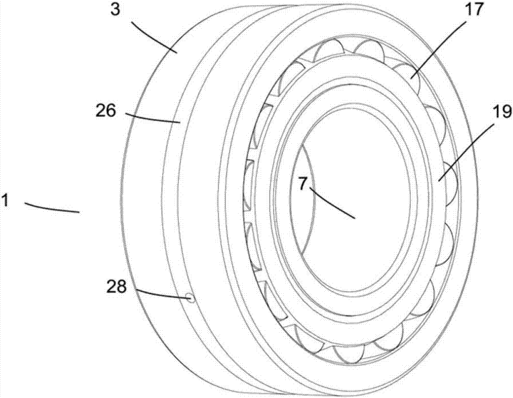
[0033] figure 1 is a perspective side view of a spherical roller bearing 1 according to one embodiment of the present invention. Due to their reliability, spherical roller bearings have been widely used in industry. They are best suited for applications characterized by heavy loads and moderate speeds, such as wind turbines, pulp and paper processing equipment, and gearboxes.

[0034] It can be seen that the spherical roller bearing 1 shown is substantially cylindrical. exist figure 1 The outer ring 3, ...


PUM


Abstract

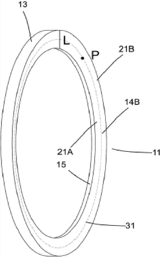
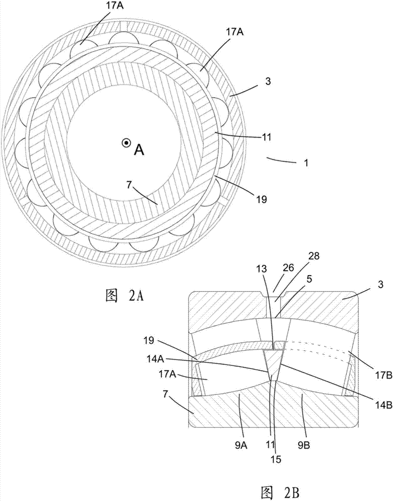
The invention discloses a spherical roller bearing which has an axially extending center axis with an outer ring, an inner ring arranged concentrically with the outer ring, a guide ring arranged concentrically with the inner ring and the outer ring, wherein the guide ring has a tapering radial cross-section, one set of cambered rollers on either side of the guide ring and a cage structure arranged to retain the two sets of cambered rollers. The guide ring has two circumferential guide ring sections, an inner guide ring section proximal to the inner ring and an outer guide ring section distal to the inner ring. At least one through-opening extends between two lateral surfaces of the guide ring. The at least one through-opening is arranged in the inner guide ring section and the cambered rollers of each set are distanced from the inner guide ring section and in contact with the outer guide ring section.

Description

technical field [0001] In general, the present invention relates to a spherical roller bearing with improved performance. Background technique [0002] Spherical roller bearings are designed to withstand large radial and axial loads. Structurally, they usually have an outer ring, an inner ring and between them two rows of oppositely arranged rolling elements separated by and interacting with guide rings (also called centering rings or spacers), for optimal load distribution. [0003] Various friction components including the above-mentioned spherical roller bearings are generally exposed to a large amount of heat generation and friction, and eventually suffer from wear. To mitigate the consequences of this exposure, various coolants and lubricants are applied. In some applications, such as gearboxes, a single substance (usually a suitable oil) is used for cooling and lubrication. By application, the oil is sprayed or washed and subsequently cooled either internally or in...

Claims


Application Information

Patent Timeline
Patent Type & Authority Applications(China)
IPC IPC(8): F16C19/38F16C33/37F16C33/48F16C33/66F16C37/00
CPCF16C19/38F16C33/37F16C33/48F16C33/6681F16C37/007F16C2360/31F16C2361/61F16C33/485F16C33/6659F16C23/086
Inventor M.洛夫
Owner AB SKF
Learn More