Temperature calibration method, to-be-tested module and temperature calibration device

A calibration method and standard module technology, applied in the field of optical communication, can solve problems such as inability to accurately output module temperature, and achieve the effect of improving accuracy and reliability

Active Publication Date: 2017-10-03
HISENSE BROADBAND MULTIMEDIA TECH
View PDF8 Cites 8 Cited by
  • Summary
  • Abstract
  • Description
  • Claims
  • Application Information

AI Technical Summary

Problems solved by technology

[0004] The invention provides a temperature calibration method, a module to be tested and a temperature calibration dev

Method used


Image

  • Temperature calibration method, to-be-tested module and temperature calibration device
  • Temperature calibration method, to-be-tested module and temperature calibration device
  • Temperature calibration method, to-be-tested module and temperature calibration device

Examples


Embodiment Construction

[0021] In order to make the purpose, technical solutions and advantages of the embodiments of the present invention more clear, the technical solutions in the embodiments of the present invention will be clearly and completely described below in conjunction with the drawings in the embodiments of the present invention.

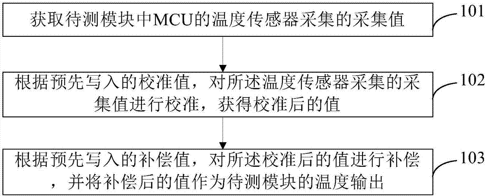
[0022] Figure 1A It is a schematic flowchart of a temperature calibration method provided by Embodiment 1 of the present invention. This embodiment is illustrated by applying the temperature calibration method to the module to be tested as an example, as Figure 1A As shown, the methods include:

[0023] 101. Obtain the collection value collected by the temperature sensor of the MCU in the module to be tested;

[0024] 102. Calibrate the collected value collected by the temperature sensor according to the pre-written calibration value to obtain a calibrated value;

[0025] 103. Compensate the calibrated value according to the pre-written compensation value, a...


PUM


Abstract

The invention provides a temperature calibration method, a to-be-tested module and a temperature calibration device. The temperature calibration method comprises the steps of: acquiring an acquisition value acquired by a temperature sensor of an MCU in the to-be-tested module; calibrating the acquisition value acquired by the temperature sensor according to a prewritten calibration value to obtain a calibrated value, wherein the calibration value is a difference between temperature output by a standard module and temperature output by the to-be-tested module; compensating for the calibrated value according to the prewritten calibration value, and outputting the compensated value as the temperature of the to-be-tested module. By adopting the temperature calibration method, the to-be-tested module and the temperature calibration device, the final output temperature value can reflect the temperature of the module truly and precisely, so as to improve the precision and reliability of temperature output by the module.

Description


Claims


Application Information

Patent Timeline
Owner HISENSE BROADBAND MULTIMEDIA TECH
Why Eureka
Try Eureka