High-thrust reluctance linear motor

A linear motor, high thrust technology, used in AC motor control, electromechanical devices, electrical components, etc., can solve problems such as low thrust density, magnetic circuit saturation, and increased iron loss.

Pending Publication Date: 2017-10-03
NANJING UNIV OF SCI & TECH +3
0 Cites 0 Cited by

AI-Extracted Technical Summary

Problems solved by technology

However, the current linear motors have the disadvantages of low thrust density and low air gap flux density, which limit the application of linear motors.
[0004] like figure 1 , figure 2 The cylindrical linear motor and the square linear motor shown have a cylindrical air gap between the stator (fixed part) and the mover (movable part...

Abstract

The invention provides a high-thrust reluctance linear motor, which comprises a stator, a rotor, a coil and an air gap, wherein the stator is provided with a core; the rotor is provided with a core; the coil is arranged in a groove of the stator core or the rotor core and is arranged to generate magnetic field force to drive the rotor to carry out linear motion relative to the stator under the external current excitation; the air gap is arranged between the stator and the rotor and is parallel to a direction of motion of the rotor, wherein the air gap is distributed in a cross section vertical to the direction of motion of the rotor in a circumferential direction in a staggered tooth shaped manner. In the design of the linear motor of the invention, the air gap is parallel to the direction of motion of the rotor and extends along a direction vertical to the direction of motion, so that the circumferential length vertical to the direction of motion of the air gap is increased, and the coupling area of the stator and the rotor is increased to be helpful for increasing the thrust.

Application Domain

AC motor controlPropulsion systems

Technology Topic

Power flowLinear motion +4

Image

  • High-thrust reluctance linear motor
  • High-thrust reluctance linear motor
  • High-thrust reluctance linear motor

Examples

  • Experimental program(1)

Example Embodiment

[0024] In order to better understand the technical content of the present invention, specific embodiments are given and described below in conjunction with the accompanying drawings.
[0025] Aspects of the invention are described in this disclosure with reference to the accompanying drawings, in which a number of illustrative embodiments are shown. Embodiments of the present disclosure are not necessarily intended to include all aspects of the invention. It should be understood that the various concepts and embodiments described above, as well as those described in greater detail below, can be implemented in any of a number of ways, as the concepts and embodiments disclosed herein do not limited to any implementation. Additionally, some aspects of the present disclosure may be used alone or in any suitable combination with other aspects of the present disclosure.
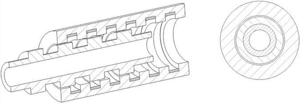
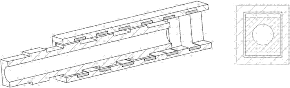
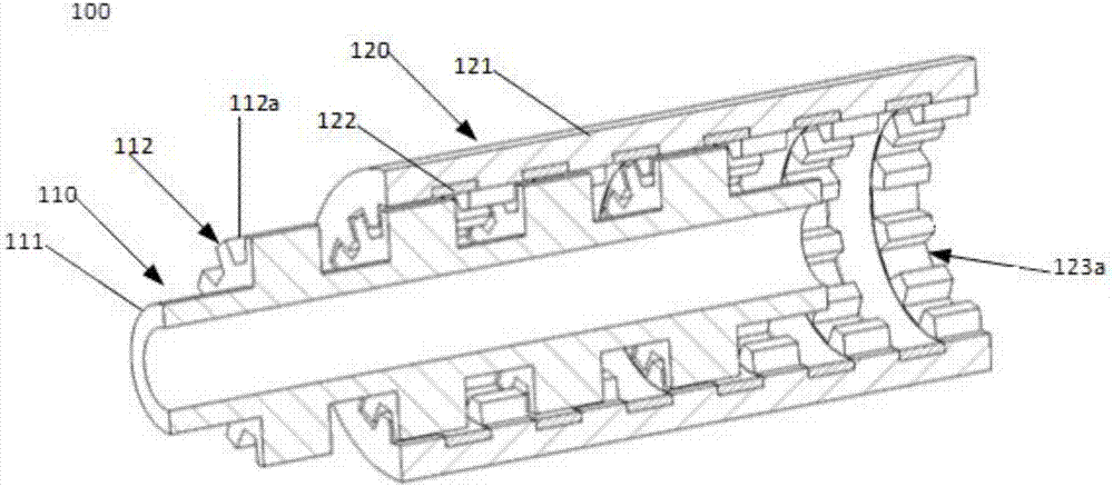
[0026] combine image 3 , Figure 4 As shown, according to an embodiment of the present invention, a high-thrust reluctance linear motor 100 is configured in a cylindrical shape and includes a mover 110, a stator 120, and an air gap 130 between the stator and the mover.
[0027] The mover 110 is configured to drive the stator 120 to perform axial linear motion relative to the stator 120 when the stator 120 is energized to generate magnetic flux.
[0028] combine image 3 , 6 , The stator 120 has a stator core 121 and a coil 122, and the coil 122 is located in the slot of the stator core.
[0029] combine Figure 4 , the air gap 130 is distributed between the stator and the mover, and the air gap is parallel to the movement direction of the mover.
[0030] In this example, the air gaps 130 are at least partially distributed in a concave-convex staggered tooth shape on a cross-section perpendicular to the moving direction of the mover.
[0031] That is to say, the air gap 130 has an extension perpendicular to the moving direction of the mover, instead of the annular smooth design structure in the prior art.
[0032] Through such a design, the length of the air gap perpendicular to the movement direction is increased, the coupling area between the stator and the mover is increased, which is beneficial to increase the thrust and improve the thrust density of the motor.
[0033] like image 3 , Figure 4 , Figure 5 As shown, the mover 110 includes a magnetic yoke 111 and a salient pole 112 disposed on the surface of the magnetic yoke. The surface of the salient pole 112 is provided with a plurality of first tooth shapes 112a, and the stator core 121 is provided with The first tooth shape 112a is adapted to a plurality of tooth slots 123a.
[0034] like image 3 , Image 6 , the tooth shapes of the first tooth profile 112a and the tooth slot 123a are substantially the same, and both adopt a trapezoidal structure design.
[0035] In other examples, the tooth shape of the first tooth shape 112a and the tooth slot 123a may also be one of a triangle, a square, a semicircle, a sine, and an involute.
[0036] In order to obtain a better thrust enhancement effect, the plurality of first tooth shapes 112 a are evenly distributed on the mover 110 , and the plurality of tooth slots 123 a are evenly distributed on the stator 120 .
[0037] It is worth mentioning that the linear motor further includes a guide device not shown, which is connected with the mover and is used to constrain the guide for movement of the mover.
[0038] Figure 7 A schematic diagram of a reluctance linear motor constructed as a square structure is shown, Figure 8 It is a cross-sectional schematic diagram of the square reluctance linear motor. As shown in the figure, the linear motor 200 also has the aforementioned mover 210 and stator 220, and an air gap 230 distributed between the stator and the mover, and the air gap 230 is parallel to the moving direction of the mover.
[0039] Depend on Figure 7 , 8 shown, the reference numeral 211 represents the mover yoke, contrast figure 2 As shown in the figure, in this example, a first tooth shape 211a is set on the yoke, and the reference numeral 221 denotes a stator core. The slots of the stator core 221 are provided with windings, and the teeth of the stator core are also provided with the same teeth as described above. The tooth slots 223 of the first tooth shape 211a are matched with each other. In this way, after the mover 210 is installed in the stator 220, the stator 220 is energized, especially the windings generate magnetic flux, and the first tooth shape 221a, the air gap 230 and the tooth slot 223 generate an attractive force, and the mover 210 is driven relative to the stator 220. move in a straight line. As a result, the air gaps 230 are at least partially distributed in the shape of teeth with staggered concavities and convexities on a cross section perpendicular to the moving direction of the mover 210 . That is, the air gap 230 has an extension perpendicular to the moving direction of the mover, instead of the annular smooth design structure in the prior art.
[0040] Through such a design, the length of the air gap perpendicular to the movement direction is increased, the coupling area between the stator and the mover is increased, which is beneficial to increase the thrust and improve the thrust density of the motor.
[0041] like image 3 , Figure 7 reluctance linear motor, combined with Figure 4 , Figure 8 As shown, its operation process is as follows:
[0042] The stator coil 122 of the reluctance linear motor is energized to generate a magnetic flux, and the magnetic flux passes through the tooth slot 123a of the stator 120, the air gap 130 and the first tooth shape 112a of the mover and is closed to generate an attractive force;
[0043] The mover 120 of the reluctance linear motor is subjected to the action of the attractive force to perform axial linear motion relative to the stator.
[0044] At the same time, when the mover moves, it is also guided by the guide device to make it move in a straight line in the same direction.
[0045] The reluctance linear motor uses the principle of minimum reluctance, that is, the magnetic flux generated by the coil is closed along the path with the minimum reluctance, and the suction force between the stator and the tooth pole of the mover is used to pull the mover to move in a straight line. combine Figure 3-5As shown, in the reluctance linear motor proposed in the foregoing embodiments, the air gap between the stator and the mover is uniformly distributed in the radial direction and has an extension in the radial direction, and the cross section perpendicular to the moving direction of the mover is at least partially uneven. The staggered tooth distribution, after the coil is energized, the magnetic flux generated by the coil is closed through the tooth shape of the stator tooth pole, the air gap and the tooth shape of the mover. The interaction area between the tooth shapes has a great influence. Through the design proposed in the present invention, the coupling area can be increased, and the thrust density can be improved.
[0046] combine figure 1 , figure 2 As shown in the prior art reluctance linear motor, the present invention designs the stator and the mover as a multi-tooth structure on the basis of the traditional reluctance linear motor structure, such as image 3 , 4 As shown, as described above, the linear motor designed in this scheme has the following significant advantages: 1) The interaction area between the stator and the mover tooth poles is effectively increased, and the magnetic field lines are respectively closed through the tooth top, tooth root and tooth surface; 2) The circumferential length of the air gap is increased, and due to the dispersion of the closed path of the magnetic field lines, the magnetic saturation of the air gap is effectively reduced. In the case of ensuring that the magnetic flux of the magnetic conductive material is not saturated, a larger current is allowed to pass through. resulting in greater attraction.
[0047] Although the present invention has been disclosed above with preferred embodiments, it is not intended to limit the present invention. Those skilled in the art to which the present invention pertains can make various changes and modifications without departing from the spirit and scope of the present invention. Therefore, the protection scope of the present invention should be determined according to the claims.

PUM

no PUM

Description & Claims & Application Information

We can also present the details of the Description, Claims and Application information to help users get a comprehensive understanding of the technical details of the patent, such as background art, summary of invention, brief description of drawings, description of embodiments, and other original content. On the other hand, users can also determine the specific scope of protection of the technology through the list of claims; as well as understand the changes in the life cycle of the technology with the presentation of the patent timeline. Login to view more.
Why Eureka
Try Eureka