Glass breaking device

A crushing device and glass technology, applied in grain processing, etc., can solve the problems of hidden safety hazards, low utilization rate, high cost, etc., and achieve the effects of prolonging service life, good use effect and small vibration

Inactive Publication Date: 2017-10-10
NANJING CHAOYANG GLASS CO LTD
View PDF0 Cites 6 Cited by
  • Summary
  • Abstract
  • Description
  • Claims
  • Application Information

AI Technical Summary

Problems solved by technology

[0002] When the existing glass crusher breaks glass, broken glass chips often fly out from the feeding port, which may accidentally injure people
And the existing glass breaker all is to break the large piece of glass first after breaking the glass, and then the small glass piece after the smashing is transported to the crushing device for crushing treatment. The smashing of the large piece of glass is generally done manually Completed, there are certain security risks
The structure of the crushing rotor in the glass crusher is generally an integral structure, that is, the hammer disc is welded on the rotating shaft. The utilization rate of this kind of structural material is low. After a certain hammer disc is damaged, the rotor needs to be replaced as a whole, and the cost is high.
In order to overcome this defect, some manufacturers produce a detachable rotor, the structure of which is as follows Figure 9 As shown, the hammer plate is set on the rotating shaft at a certain interval, and the hammer plate and the rotating shaft are connected by keys, the connecting shaft is installed on the hammer plate along the direction of the rotating shaft, and the hammer 410 is sleeved on the connecting shaft. The impact hammer 410 in this structure has no limit between the two hammer plates. During the rotation of the rotor, the impact hammer 410 will swing in the axial direction, which will cause the overall vibration of the crusher to be large, and the impact hammer 410 will hit the hammer plate, affecting the service life of the whole crusher

Method used


Image

  • Glass breaking device
  • Glass breaking device
  • Glass breaking device

Examples


Embodiment Construction

[0029] The present invention will be further described below in conjunction with the accompanying drawings.

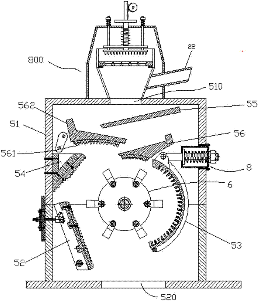
[0030] Such as figure 1 As shown, the present invention discloses a crushing device for crushing glass, which includes a crushing shell 51, on which is provided a feed port 510 and a discharge port 520, and also includes a bar-shaped counterattack plate 52, an arc counterattack Plate 53, counterattack block 54, first material guide baffle 55, second material guide baffle 56, rotor 6 and crushing mechanism 800, rotor 6 is rotatably connected in crushing shell 51, strip counterattack plate 52 and counterattack block 54 It is arranged on the left side of the rotor 6, and the counter-attack block 54 is located at the upper end of the strip-shaped counter-attack plate 52, and the arc-shaped counter-attack plate 53 is located on the right side of the rotor 6, a first material guide baffle 55 and two second material guide baffles 56 are layered from top to bottom below the ...


PUM


Abstract

The invention discloses a crushing device for crushing glass, which comprises a crushing shell, which is provided with a feed port and a discharge port, and also includes a strip-shaped counterattack plate, an arc counterattack plate, a counterattack block, and a first counterattack block. A material guide baffle, a second material guide baffle, a rotor and a crushing mechanism, the rotor is rotatably connected in the crushing shell, the strip counterattack plate and the counterattack block are arranged on the left side of the rotor, and the arc counterattack plate is arranged on the side of the rotor On the right side, a first material guide baffle and two second material guide baffles are layered up and down below the feed inlet, and the crushing mechanism is fixed on the outer wall of the crushing shell. The invention can effectively prevent broken glass chips from flying out from the feeding port, and avoid accidentally injuring people; after the large pieces of glass are broken, they will directly enter the crushing shell, with high efficiency. The plate is crushed, and at the same time, it can be used for large and small glass blocks, and the use effect is good. The limit unit can effectively prevent the axial displacement of the hammer head.

Description

Technical field: [0001] The invention relates to a breaking device for breaking glass. Background technique: [0002] When the existing glass breaker breaks glass, broken glass chips often fly out from the feed port, thereby accidentally injuring people. And the existing glass breaker all is to break the large piece of glass first after breaking the glass, and then the small glass piece after the smashing is transported to the crushing device for crushing treatment. The smashing of the large piece of glass is generally done manually Completed, there are certain security risks. The structure of the crushing rotor in the glass crusher is generally an integral structure, that is, the hammer disc is welded on the rotating shaft. The utilization rate of this kind of structural material is low. After a certain hammer disc is damaged, the rotor needs to be replaced as a whole, which is costly. In order to overcome this defect, some manufacturers produce a detachable rotor, the st...

Claims


Application Information

Patent Timeline
Patent Type & Authority Applications(China)
IPC IPC(8): B02C13/09B02C13/28B02C13/286
CPCB02C13/09B02C1/14B02C13/2804B02C13/286B02C2013/2812B02C2013/28618
Inventor 李志根
Owner NANJING CHAOYANG GLASS CO LTD
Why Eureka
Try Eureka