Engine exhaust heat utilization system and control method of the same

A control method and engine technology, applied in engine components, combustion engines, machines/engines, etc., can solve problems such as waste of exhaust heat, and achieve the effect of avoiding energy waste

Pending Publication Date: 2017-10-10
高志男
View PDF7 Cites 3 Cited by
  • Summary
  • Abstract
  • Description
  • Claims
  • Application Information

AI Technical Summary

Problems solved by technology

[0003] In view of this, the present invention provides an engine exhaust heat utilization system and its control method, the main purpose of which is to solve the technical problem of waste of heat in the exhaust caused by the exhaust of the existing engine being directly discharged into the atmosphere

Method used


Image

  • Engine exhaust heat utilization system and control method of the same

Examples


Embodiment Construction

[0030] In order to further explain the technical means and effects of the present invention to achieve the intended purpose of the invention, the specific implementation, structure, features and effects of the application according to the present invention will be described in detail below in conjunction with the accompanying drawings and preferred embodiments. . In the following description, different "one embodiment" or "embodiment" do not necessarily refer to the same embodiment. Furthermore, the particular features, structures, or characteristics of one or more embodiments may be combined in any suitable manner.

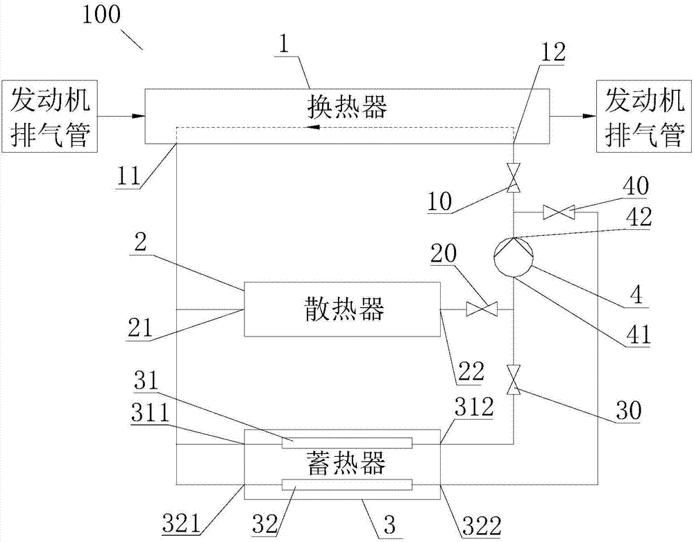
[0031] Such as figure 1 As shown, an engine exhaust heat utilization system 100 proposed by an embodiment of the present invention includes a heat exchanger 1 , a radiator 2 , a heat accumulator 3 and a compression device 4 . The heat exchanger 1 is used for receiving the exhaust gas of the engine, and exchanging heat between the exhaust gas of the engine and t...


PUM


Abstract

The invention discloses an engine exhaust heat utilization system and control method of the same, which relate to the field of engine, and the main purpose is to solve the technical problem that the exhaust of the existing engine is directly discharged into the atmosphere causing the waste of heat in the exhaust. The mainly adopted technical scheme includes that the engine exhaust heat utilization system includes a heat exchanger, a radiator, a heat accumulator, a compression device and a control device. The heat exchanger is used to receive the exhaust of the engine, thereby exchanging heat in the exhaust of the engine and the fluid flowing through the heat exchanger. The heat accumulator has a heat accumulation channel for heat accumulation and a heat release channel for heat release. One end of the radiator and one end of the heat accumulation channel are both used to connect to one end of the heat exchanger. The other end of the radiator and the other end of heat accumulation channel are both connected to one end of the compression device. The other end of the compression device is connected to the other end of the heat exchanger. The engine exhaust heat utilization system can reasonably utilize and store the heat in the exhaust of the engine to avoid the waste of energy.

Description

technical field [0001] The invention relates to the technical field of engines, in particular to an engine exhaust heat utilization system and a control method thereof. Background technique [0002] At present, when the engine is working, its exhaust gas is directly discharged into the atmosphere, which not only pollutes the atmosphere, but also discharges the heat in the exhaust gas into the air, resulting in a large waste of heat. Contents of the invention [0003] In view of this, the present invention provides an engine exhaust heat utilization system and its control method, the main purpose of which is to solve the technical problem of waste of heat in the exhaust caused by the exhaust of the existing engine being directly discharged into the atmosphere. [0004] In order to achieve the above object, the present invention mainly provides the following technical solutions: [0005] On the one hand, an embodiment of the present invention provides an engine exhaust heat...

Claims


Application Information

Patent Timeline
Patent Type & Authority Applications(China)
IPC IPC(8): B60H1/20F02G5/02
CPCF02G5/02B60H1/20F02G2254/40Y02T10/12
Inventor 高志男柴雅丽
Owner 高志男
Why Eureka
Try Eureka