Grouting device and grouting method

A grouting device and grouting technology, applied in construction, sheet pile wall, infrastructure engineering and other directions, can solve the problems of inconvenient construction operation, poor economy, increased construction investment, etc., to facilitate construction installation and disassembly, and ensure uniformity. Continuity and the effect of improving the bearing capacity of a single pile

Active Publication Date: 2017-10-10
WUHAN UNIV
View PDF6 Cites 15 Cited by
  • Summary
  • Abstract
  • Description
  • Claims
  • Application Information

AI Technical Summary

Problems solved by technology

[0003] When the bored pile needs to be constructed, the hole is usually drilled first, then the steel cage is placed in the pile hole, and the pile body concrete is poured at last; large-scale drilling machinery, steel cage lifting equipment and concrete mixer are required, the construction period is long, and the pile body concrete Difficult to guarantee quality
If prefabricated pipe piles are used as the foundation of transmission line towers, the pile diameter should not be less than 800mm, and the requirements for piling or pile pressing equipment are high, and excessive piling or pile pressing force may cause damage to the pile body, which is not convenient for transmission lines in mountainous areas Application in engineering
[0004] The common simple grouting device in the past is to pre-bury two grouting pipes at the symmetrical position outside the pipe pile between the hole walls, and start grouting after the pile sinking reaches the specified elevation. Although this grouting method is simple, there are many problems. The problem is that grouting through the two grouting pipes at the symmetrical positions outside the pipe pile cannot guarantee the synchronous return of grout on both sides of the pipe pile, resulting in more cement and soil in the grouting liquid, and the grouting layer is prone to voids, the grouting is not dense, and the grouting The quality is difficult to guarantee; if multiple grouting machines are used to grout at the same time, the problem of asynchronous return of the grout on both sides of the pipe pile can be overcome, but the investment in grouting equipment is large, the construction operation is inconvenient and the construction investment increases. In addition, the grouting pipeline Placing the outside of the pipe pile is not conducive to the protection of the grouting pipeline during the pile sinking construction process, and it is easy to damage the grouting pipeline, resulting in the failure of the subsequent grouting process to proceed smoothly
Other types of grouting devices also have examples of placing the grouting pipeline inside the pipe pile, but the main grouting pipeline is mostly two or more grouting pipes, the construction operation is complicated, and the economy is poor. In addition, the grouting pipeline Recycling issues are also less considered

Method used


Image

  • Grouting device and grouting method
  • Grouting device and grouting method
  • Grouting device and grouting method

Examples


Embodiment Construction

[0041] The grouting device and the grouting method involved in the present invention will be described in detail below with reference to the accompanying drawings.

[0042]

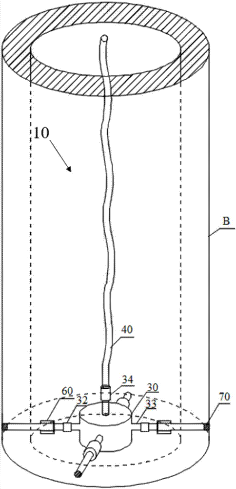
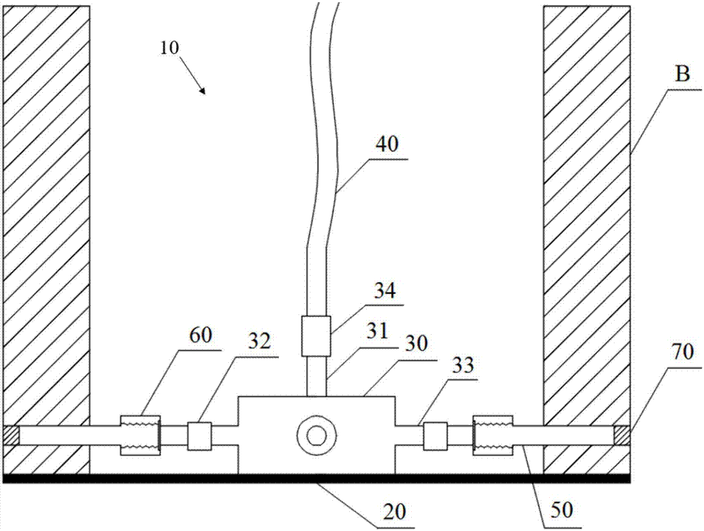
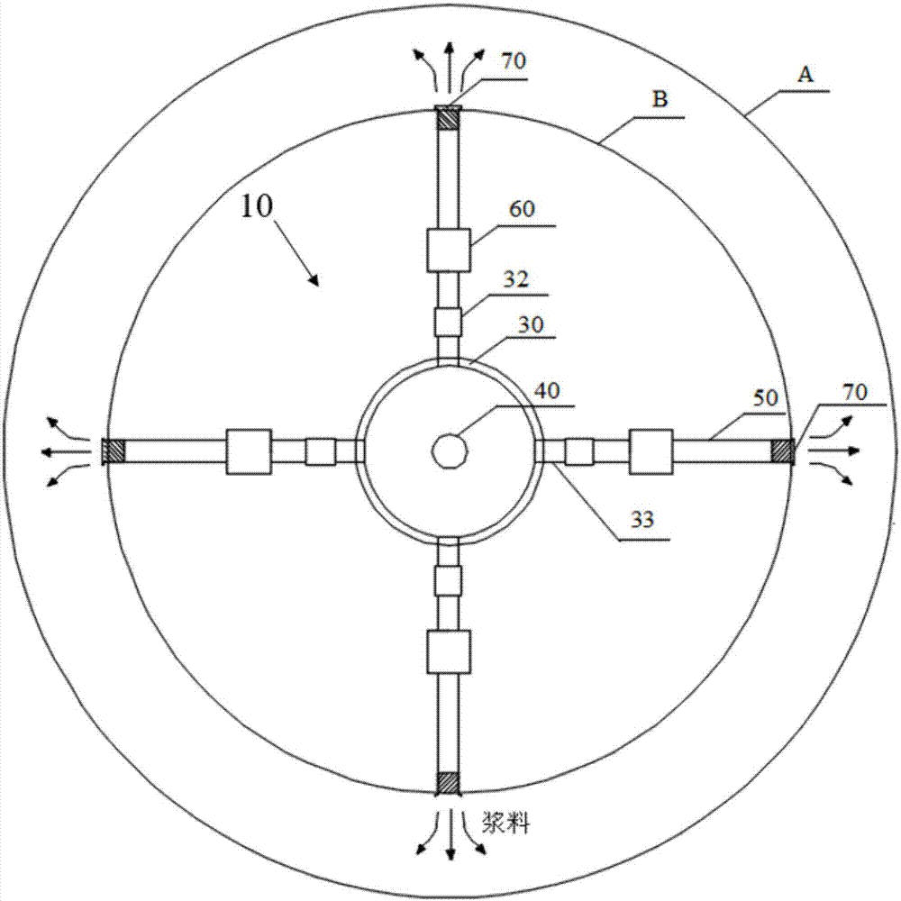
[0043] Such as Figures 1 to 3 As shown, the grouting device 10 cooperates with the prefabricated pipe pile A, and is used for grouting after the prefabricated pipe pile is put into the pile hole B with a diameter of 20 cm. It includes: an end plate 20, a grouting buffer chamber 30 , Grouting pipe 40, four outlet pipes 50, four check valves 60, and four plugs 70.

[0044] The end plate 20 is matched with the bottom end of the prefabricated pipe pile A, and is used to seal the bottom end of the prefabricated pipe pile A, so as to ensure that the inside and outside of the pile can be sealed and impermeable during the pile sinking and grouting process, and prevent the Cement slurry, water, soil, etc. enter the interior of the prefabricated pipe pile A. In this embodiment, the end plate 20 is The steel ...


PUM


Abstract

The invention provides a grouting device which is high in construction speed, simple in structure, convenient to operate, high in efficiency and economical and a corresponding grouting method. The grouting device is characterized by being matched with a prefabricated pipe pile, and the grouting device carries out grouting after the prefabricated pipe pile is put into a pile hole with a larger diameter; the grouting device comprises an end plate which is used for sealing the bottom end of the prefabricated pipe pile, a grouting cushion chamber which is arranged in the end plate and is hollow inside, a grouting pipe, a plurality of grout outlet pipes, a plurality of reversing grout stopping valves and a plurality of end caps, wherein a grouting opening is formed in the upper end of the grouting pipe, and the lower end of the grouting pipe communicates with the grouting cushion chamber; the multiple grout outlet pipes are evenly arranged on the periphery of the grouting cushion chamber, a grout inlet of each grout outlet pipe communicates with the grouting cushion chamber, grout outlets can penetrate reserved holes in the side wall of the prefabricated pipe pile and face the space to be grouted on the outer side of the prefabricated pipe pile; the multiple reversing grout stopping valves are arranged on the grout outlet pipes correspondingly and stop grout from reversely flowing in the direction from the grout outlets to the grout inlets; and the multiple end caps block the grout outlets.

Description

technical field [0001] The invention belongs to the technical field of building pile foundation engineering construction, and in particular relates to a grouting device and a corresponding grouting method. Background technique [0002] The pile foundation of transmission line pole and tower is not only required to bear vertical pressure, but also to bear horizontal load and uplift load caused by factors such as tower line and wind. The requirements for horizontal bearing capacity and uplift bearing capacity of single pile foundation are relatively high. [0003] When the bored pile needs to be constructed, the hole is usually drilled first, then the steel cage is placed in the pile hole, and the pile body concrete is poured at last; large-scale drilling machinery, steel cage lifting equipment and concrete mixer are required, the construction period is long, and the pile body concrete Quality cannot be guaranteed. If prefabricated pipe piles are used as the foundation of tra...

Claims


Application Information

Patent Timeline
Patent Type & Authority Applications(China)
IPC IPC(8): E02D15/04E02D5/62E02D5/50
CPCE02D5/50E02D5/62E02D15/04
Inventor 傅旭东吕布杨之俊张本蛟梅灿黄斌张雨廷徐士高黄启乐贺云贾耀民
Owner WUHAN UNIV
Why Eureka
Try Eureka