Toilet flushing system based on negative pressure drainage

A technology of negative pressure and water tank, which is applied in the field of sanitary ware, can solve the problems of complex structure and high cost, and achieve the effect of low cost, simple structure and saving water resources

Active Publication Date: 2017-10-10
JIANGSU UNIV
View PDF9 Cites 1 Cited by
  • Summary
  • Abstract
  • Description
  • Claims
  • Application Information

AI Technical Summary

Problems solved by technology

A scheme proposed by CN105714895A, a positive and negative pressure combined pneumatic

Method used


Image

  • Toilet flushing system based on negative pressure drainage
  • Toilet flushing system based on negative pressure drainage

Examples


Embodiment approach

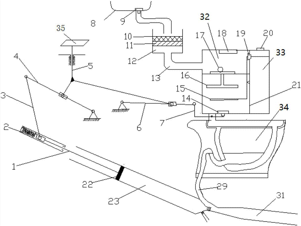
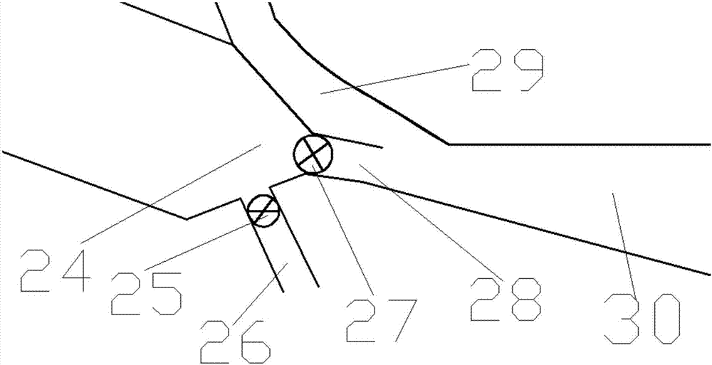
[0035] figure 1 Shown is an embodiment of the toilet flushing system based on negative pressure drainage in the present invention, and the toilet flushing system based on negative pressure drainage includes a mechanical linkage device, a water tank, a washbasin 8, a waste water treatment tank 12, a water tank inlet Water pipe 13, valve 14, buoyancy rod 15, floater 16, plug 19, partition 21, piston 22, air storage chamber 23, contraction section 24, one-way valve 25, conduit 26, one-way valve 27, throat pipe 28, Siphon elbow 29, diffusion section 30, sewage pipe 31 and toilet 34.

[0036] The water tank is divided into a water tank A32 and a water tank B33 by a partition 21. The water tank A32 is connected to the bottom of the waste water treatment tank 12 through the water tank inlet pipe 13, and the waste water treatment tank 12 is connected to the lavatory 8 through a pipeline. A strainer 9 is provided at the connection between the pool 8 and the waste water treatment tank ...


PUM


Abstract

The invention provides a toilet flushing system based on negative pressure drainage, the toilet flushing system includes a mechanical linkage device, a water tank, a wash basin, a wastewater treatment tank, a water inlet pipe of the water tank, a valve, a buoyancy rod, a floater, a plug, a diaphragm, a piston, a gas storage chamber, a contraction section, one one-way valve, a guide pipe, another one-way valve, a throat pipe, a siphon bend, a divergent section, a drainage pipe, and a toilet. The mechanical linkage device is connected with the water tank and a Venturi pipe, the water tank includes a tank body A and a tank body B, and the tank bodies of A and B are equipped with purified recycled water for life and tap water respectively. The throat of the Venturi pipe is connected with the siphon bend of the toilet. When the mechanical linkage device is triggered, the water of the tank body A flushes the toilet, at the same time, a jet flow is formed at the throat, and the momentum of the dirt discharged with the drainage is increased. Through the mixture design of the siphon and the Venturi pipe, the siphonage is formed when the flushing water is not large, the piston is mainly driven by the linkage device to pressurize the gas in the gas storage chamber, and a high velocity flowing fluid is formed in the throat so as to produce the adsorption effect.

Description

technical field [0001] The invention belongs to the field of sanitary ware, and in particular relates to a novel toilet flushing system based on negative pressure drainage. Background technique [0002] The currently used siphon toilet uses free water pressure difference to press or spray water and dirt into the siphon of the toilet. The siphon tube refers to the shape bend under the toilet. When the water surface in the toilet exceeds the high point of the bend during sewage discharge, a siphon phenomenon is formed, and the water and dirt in the toilet can be sucked away until only a small amount of water is left. , the siphon is broken, leaving a small amount of water, forming a water seal. This closet requires a large amount of water to discharge the dirt during the blowdown process. [0003] At present, there are research results of using negative pressure to assist the sewage discharge of siphon toilet to save water resources. In CN102776937A, an energy-saving toilet...

Claims


Application Information

Patent Timeline
IPC IPC(8): E03D1/30E03D1/33E03D1/36E03D11/18
CPCE03D1/302E03D1/33E03D1/36E03D11/18E03D2201/30
Inventor 于龙杰刘栋胡兵
Owner JIANGSU UNIV
Why Eureka
Try Eureka