Floor drain device

A floor drain and knob technology, applied in water supply devices, waterway systems, buildings, etc., can solve the problems of not considering the anti-blocking or anti-blocking effect of water pipes, not having the ability to control water flow/break, and drainage pipe blockage, etc., to achieve simple connection methods , wide application range, labor-saving effect

Active Publication Date: 2017-10-10
ANHUI POLYTECHNIC UNIV MECHANICAL & ELECTRICAL COLLEGE
View PDF7 Cites 1 Cited by
  • Summary
  • Abstract
  • Description
  • Claims
  • Application Information

AI Technical Summary

Problems solved by technology

[0003] However, the common floor drains have some shortcomings and deficiencies. For example, the usual floor drains only consider the drainage function, and do not have the function of controlling the flow of water. When using water or isolating

Method used


Image

  • Floor drain device
  • Floor drain device
  • Floor drain device

Examples


Embodiment 1

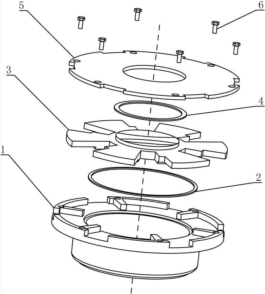
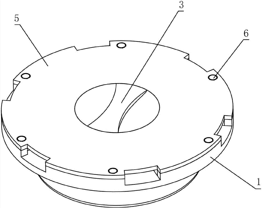
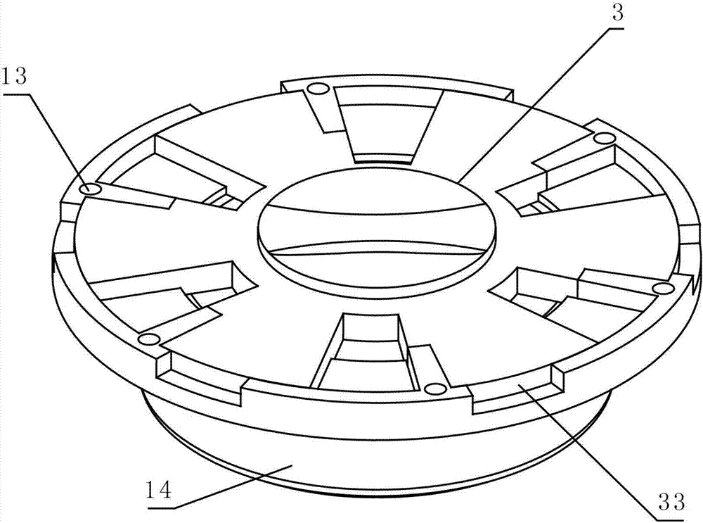
[0039] see figure 1 , figure 2 , image 3 , a floor drain device is provided in this embodiment, which includes a base 1, a knob 3, a top cover 5, and a bolt 6. The inner wall of the base 1 is provided with a first step 11, and one surface perpendicular to the axis A number of baffles 12 are provided, and threaded holes 13 are provided on the baffle 12, and a flange 14 is provided on the other surface. The specific structure of the base 1 is as follows: Figure 5 shown;

[0040] One surface of the knob 3 is provided with a handle 31, the other surface is provided with a second step 32, and several blades 33 are provided along the circumferential direction of the axis of the knob 3. The specific structure is as follows: Figure 6 , Figure 7 As shown, the number of the blades 33 is the same as the number of the baffles 12; the first step 11 is matched with the second step 32 to realize the connection between the knob 3 and the base 1, any of the blades 33 can rotate back ...

Embodiment 2

[0046] The main difference between this embodiment 2 and the above-mentioned embodiment 1 is that this embodiment also includes a slag trap 7, such as Figure 9 As shown, the slag trap 7 is cylindrical, the side and / or bottom surface of the slag trap 7 is provided with a number of holes 71, and the inner surface of one end of the flange 14 is provided with an internal thread for connecting the The slag separator 7, which can filter the scum or foreign matter in the water flow, further improves the anti-blocking effect of the floor drain device, and can avoid the blockage of the pipeline as much as possible.

[0047] Preferably, in this embodiment, the hole 71 opened on the slag separator 7 is a circular hole, which is convenient for processing and forming, and at the same time facilitates the circulation of water flow.

Embodiment 3

[0049] The main difference between this embodiment 3 and the above-mentioned embodiment 2 is that in this embodiment, the floor drain device is installed on the pipeline with grooves, such as Figure 10 , Figure 11 , Figure 12 as well as Figure 13 shown, where Figure 10 , the knob 3 of the floor drain device is in a closed state, and the water flow on the ground cannot enter the pipeline 8 through the floor drain device, and in Figure 12 Among them, the knob 3 of the floor drain device is in a fully open state, and the water flow on the ground can enter the pipeline 8 through the floor drain device, and the path and direction of the water flow are as follows: Figure 13 As shown by the curve with the arrow in the middle, the water flow entering the floor drain device flows into the pipeline after being further filtered by the slag separator 7, and the filter residue effect is obvious.


PUM


Abstract

The invention relates to a floor drain device which comprises a base, a rotary knob, a top cover and bolts. A first step is arranged on the inner wall of the base, a plurality of baffles are arranged on one face perpendicular to the axis, threaded holes are formed in the baffles, and a flange is arranged on the other face. A handle is arranged on one face of the rotary knob, a second step is arranged on the other face, and a plurality of blades are arranged in the circumferential direction of the axis of the rotary knob. The first step is matched with the second step to achieve connection of the rotary knob and the base, and any blade can rotate between the two corresponding adjacent blades back/forth to control on/off of water flow. The top cover is a circular plate, a plurality of groove openings are formed in the circumferential direction of the edge of the top cover, and the top cover is connected to the base through the bolts. The floor drain device is convenient to install, can control on/off of water flow and has the advantages of being good in anti-blocking effect, capable of preventing peculiar smell or bugs, wide in application range and the like.

Description

technical field [0001] The invention relates to the technical field of floor drain devices, in particular to a floor drain device with good anti-blocking effect and capable of preventing peculiar smell or bugs. Background technique [0002] The floor drain is an important interface connecting the drainage pipe system and the indoor ground. As an important part of the drainage system in the residence, its performance directly affects the discharge of indoor sewage and indoor air quality. [0003] Now common floor drains have some shortcomings and deficiencies. For example, the usual floor drains only consider the drainage function and do not have the function of controlling water flow / stop. When it is necessary to store water or isolate odors or bugs in the drainage pipes, it cannot satisfy users. Secondly, the anti-blocking effect of water pipes is not considered or the effect of anti-blocking is poor, resulting in frequent blockage of drainage pipes, which is very troubleso...

Claims


Application Information

Patent Timeline
IPC IPC(8): E03F5/04
CPCE03F5/0407E03F5/0411E03F2005/0417
Inventor 霍美香袁卫家万家山
Owner ANHUI POLYTECHNIC UNIV MECHANICAL & ELECTRICAL COLLEGE
Why Eureka
Try Eureka