Split lens and camera module

A split-type lens technology, which is applied in the field of split-type lenses and camera modules, can solve problems such as low precision, unguaranteed imaging quality, and large assembly errors of camera modules, achieving good precision, improving matching accuracy and imaging quality, The effect of high placement rate

Pending Publication Date: 2017-10-10
ZHEJIANG SUNNY OPTICAL CO LTD
View PDF6 Cites 7 Cited by
  • Summary
  • Abstract
  • Description
  • Claims
  • Application Information

AI Technical Summary

Problems solved by technology

[0004] Conventional high-pixel module solutions use module alignment technology to improve quality through the correction of the entire image lens. Such alignment methods have low accuracy, and the assembly error of the camera module is large, and the imaging quality cannot be guaranteed.

Method used


Image

  • Split lens and camera module
  • Split lens and camera module
  • Split lens and camera module

Examples


Embodiment approach

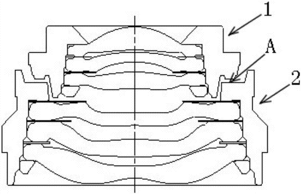
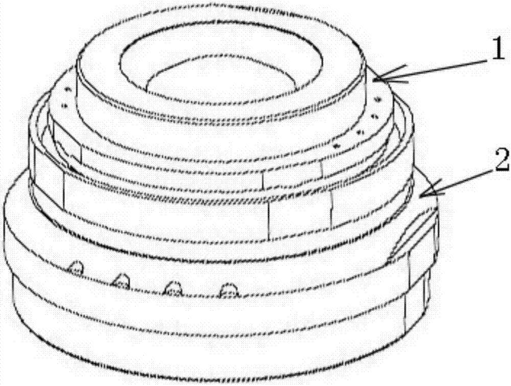
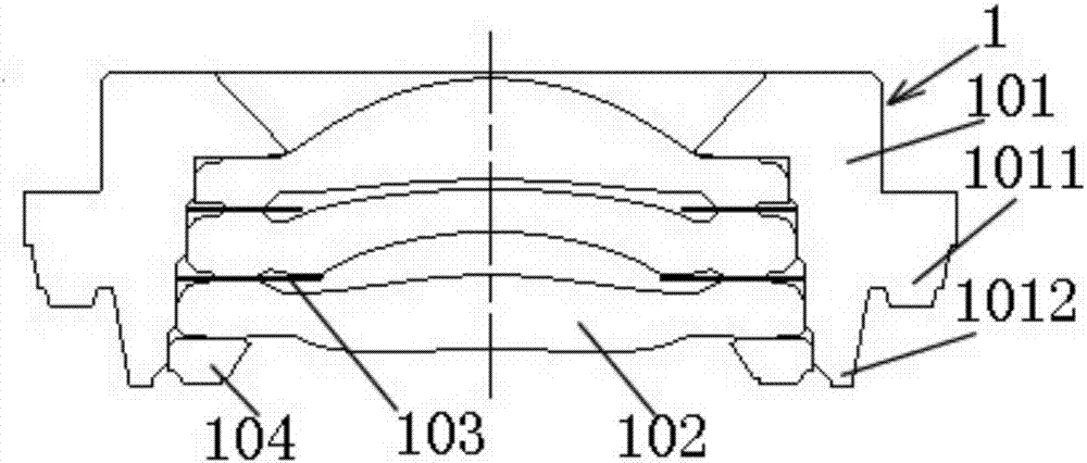
[0059] According to one embodiment of the present invention, when assembling the camera module with the above-mentioned split lens according to the present invention, because the diaphragm is arranged in one of the lens barrels of the split lens, it is no longer necessary to spend time assembling the diaphragm , In addition, because the assembly of the split lens is convenient and fast, the speed of assembling the camera module according to the present invention is faster, compared with the assembly method of the camera module containing the split lens in the prior art, it can save a lot of The assembly time is very high, and the assembly efficiency is very high, while ensuring the matching accuracy and imaging quality of the camera module.


PUM


Abstract

The invention relates to a split lens, which comprises an independent object side group forming a free end of the split lens, at least one independent image side group and a diaphragm, wherein the independent image side groups and the independent object side group are sequentially arranged and fixedly connected; and a fit clearance is formed between the object side group and the image side groups. According to the split lens, alignment is freer and more flexible, assembly is convenient and fast and the coordinating precision is high.

Description

technical field [0001] The invention relates to a split lens and a camera module comprising the split lens. Background technique [0002] The lens groups of the existing split lenses do not have matching gaps and specific structural fits, so the upper lens group cannot be accurately adjusted relative to the lower lens group, and the matching accuracy of the upper and lower lens groups is low. This also leads to a low yield rate of the split lens, and the image quality is not good enough. [0003] At this stage, the requirements for high-end video lenses are getting higher and higher. In order to improve the yield rate of the module process and shorten the auto-focus time, research on new process technology has become the direction of everyone's efforts. [0004] Conventional high-pixel module solutions use module alignment technology to improve quality through the correction of the entire image lens. Such alignment methods have low accuracy, large assembly errors in camera ...

Claims


Application Information

Patent Timeline
Patent Type & Authority Applications(China)
IPC IPC(8): G02B7/02
CPCG02B7/023
Inventor 张芳
Owner ZHEJIANG SUNNY OPTICAL CO LTD
Why Eureka
Try Eureka