Polishing vacuum absorption device capable of improving absorption efficiency

A technology of vacuum adsorption and high efficiency, which is applied in the direction of grinding feed movement, grinding workpiece support, grinding machine tool parts, etc., can solve the problems of increasing production cost of enterprises, reducing negative pressure performance, and limited actual effect, and achieves saving Improved cost, improved adsorption performance, and enhanced adsorption performance

Active Publication Date: 2017-10-13
苏州尚品科技有限公司
View PDF6 Cites 2 Cited by
  • Summary
  • Abstract
  • Description
  • Claims
  • Application Information

AI Technical Summary

Problems solved by technology

[0004] However, the problems exposed by the known above-mentioned adsorption devices during long-term use are:
[0005] The suction force of the negative pressure chamber for the workpiece is often not enough, and the adsorption efficiency is not high. The reason is that when the belt runs so that the upper opening matches the adsorption hole on the adsorption cover plate, the actual adsorption hole that works on the adsorption workpiece is very small. less, while the rest of the adsorption holes ventilate with the outside world (air leakage) through the openings, which reduces the negative pressure performance in the negative pressure chamber and affects the adsorption efficiency.
[0006] In order to solve the above problems, the current improvement measures are usually to replace the high-power vacuum equipment to enhance the suction, but the actual effect is limited, and it increases the production cost of the enterprise

Method used


Image

  • Polishing vacuum absorption device capable of improving absorption efficiency
  • Polishing vacuum absorption device capable of improving absorption efficiency
  • Polishing vacuum absorption device capable of improving absorption efficiency

Examples


Embodiment

[0024] Embodiment: Below in conjunction with Figure 1~3 The structural principle of the present invention is described in detail, and this embodiment exemplifies a special case of the present invention.

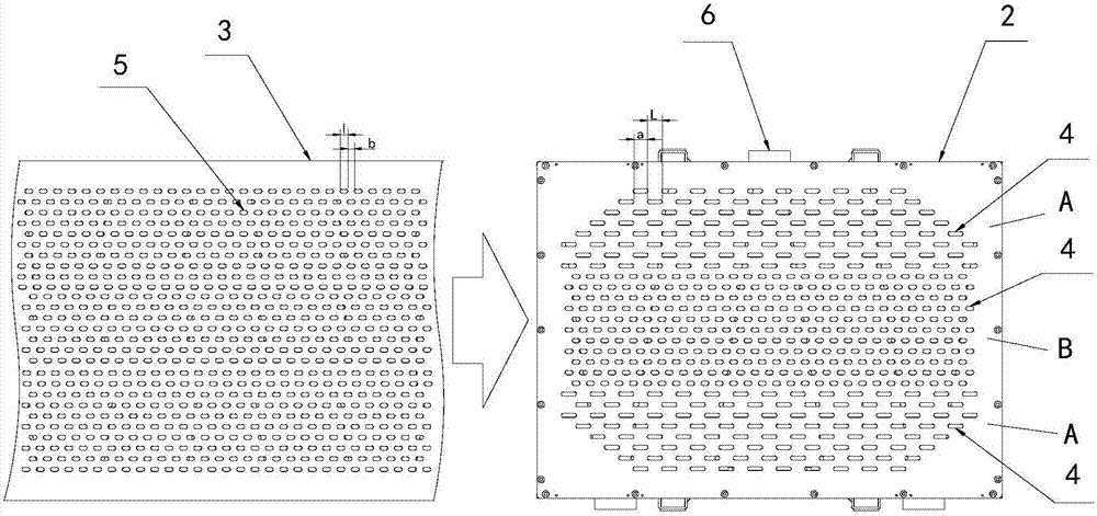
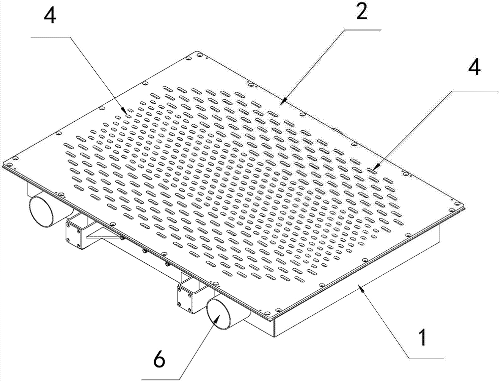
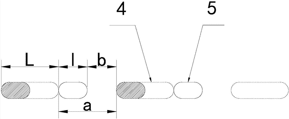
[0025] Such as figure 1 and figure 2 The shown grinding vacuum adsorption device that can enhance the adsorption efficiency has a negative pressure chamber 1, an adsorption cover 2 fixed on the upper part of the negative pressure chamber 1, and an adsorption cover 2 above the adsorption cover 2 for transporting workpieces. The transmission belt 3, the adsorption cover plate 2 is provided with several rows of adsorption holes 4 along the moving direction of the transmission belt 3, the adsorption holes 4 in each row are evenly spaced, and the transmission belt 3 corresponds to the rows below it. The adsorption holes are provided with several rows of openings 5, and the openings 5 ​​in each row are also evenly spaced. The negative pressure chamber 1 is provided with a sucti...


PUM


Abstract

The invention discloses a polishing vacuum absorption device capable of improving absorption efficiency. The device comprises a negative-pressure cavity, an absorption cover plate, and a conveying belt positioned above the absorption cover plate; the absorption cover plate is provided with multiple rows of absorption holes in the motion direction of the conveying belt; each row of absorption holes are uniformly distributed at intervals; the conveying belt is provided with multiple rows of open holes corresponding to each row of absorption holes on the lower side; each row of open holes are uniformly distributed at intervals; the negative-pressure cavity is provided with an air sucking port for connecting with vacuumizing equipment by a pipeline; the absorption cover plate is provided with staggered absorbing areas; a gap between front and back adjacent absorption holes in each row is a; the length of each absorption hole is L; a gap between front and back adjacent open holes in each row on the conveying belt is b; the length of each open hole is l; L is bigger than l and smaller than 2l+b; meanwhile, a is smaller than 2l+b and bigger than b; a, L, b and l are all bigger than 0; and when the conveying belt is operated, only part of open holes always communicate with the absorption holes in the staggered absorption areas. The device can achieve excellent absorption efficiency without needing to increasing the power of the vacuumizing equipment.

Description

technical field [0001] The invention relates to a grinding vacuum adsorption device capable of enhancing adsorption efficiency. Background technique [0002] Because there is no assembly and disassembly process compared with traditional positioning tooling, it can simplify operations and improve efficiency. It is known that enterprises use vacuum adsorption devices to absorb and fix workpieces on the conveyor belt when they streamline and polish workpieces. [0003] The current common vacuum adsorption device mainly includes a negative pressure chamber, an adsorption cover, pipelines and vacuuming equipment. The negative pressure chamber is formed by enclosing and splicing the bottom plate and the surrounding side plates. The adsorption cover is fixed on the upper part of the negative pressure chamber. The adsorption cover is densely covered with adsorption holes, and the transmission belt above the adsorption cover is usually densely covered with holes hole. The side plat...

Claims


Application Information

Patent Timeline
Patent Type & Authority Applications(China)
IPC IPC(8): B24B41/00B24B41/06
CPCB24B41/005B24B41/06
Inventor 曹明星
Owner 苏州尚品科技有限公司
Why Eureka
Try Eureka