Nozzle deposit removing device and method of nozzle deposit removal

Active Publication Date: 2020-07-30
HONDA MOTOR CO LTD
View PDF0 Cites 1 Cited by
  • Summary
  • Abstract
  • Description
  • Claims
  • Application Information

AI Technical Summary

Benefits of technology

The invention is about a device that removes deposits from a nozzle using a negative pressure effect. By supplying a moderate amount of fluid, the device can remove the nozzle deposits without needing to stop or wipe them off. The device can also increase the negative pressure effect by adjusting the gap between the nozzle and the tip, allowing for easier removal of the materials. Overall, the invention allows for efficient and cost-effective cleaning of the nozzle without the need for additional labor.

Problems solved by technology

However, in the case where a gap between the nozzle and a blowout port of the compressed air is large, an air supply source of large supply pressure must be used in order to remove the application material that has attached to the tip of the nozzle.
As a result, a device ends up increasing in size.

Method used


Image

  • Nozzle deposit removing device and method of nozzle deposit removal
  • Nozzle deposit removing device and method of nozzle deposit removal
  • Nozzle deposit removing device and method of nozzle deposit removal

Examples


first modified example

4.1 First Modified Example

[0054]In the first modified example shown in FIG. 5, another air supply source 60 and an air blow nozzle 62 (a fluid supplying unit) connected to the other air supply source 60 are provided.

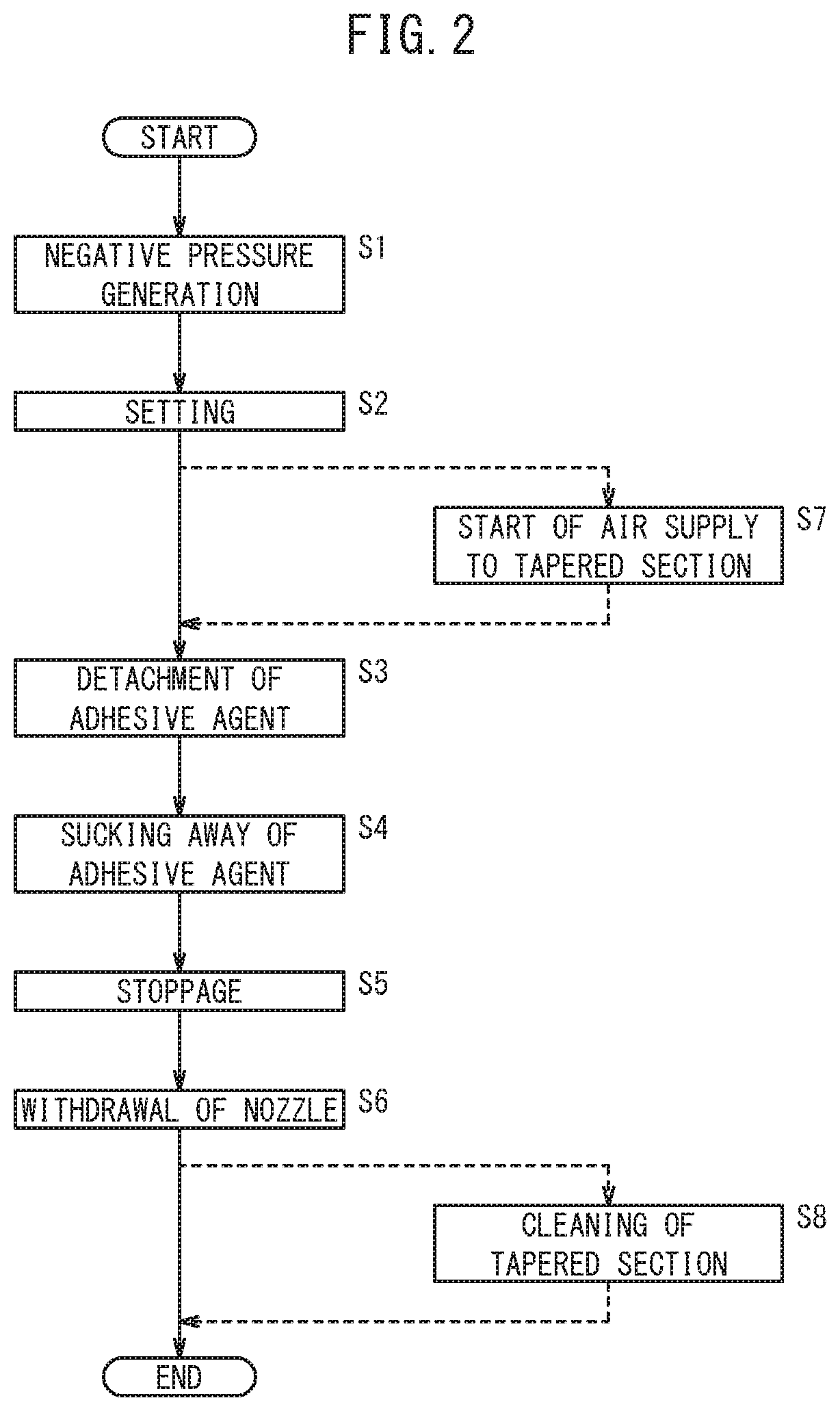
[0055]Moreover, in the first modified example, after step S2 of FIG. 2, operation proceeds to step S7, and the controller 18 drives the other air supply source 60, and starts supply of compressed air to the air blow nozzle 62 from the other air supply source 60. The air blow nozzle 62 is disposed in a vicinity of the large diameter portion 28a of the tapered section 28, and the compressed air supplied from the other air supply source 60 is jetted (supplied) toward the through-hole 30 via the gap 32 from the large diameter portion 28a of the tapered section 28.

[0056]Thus, in step S3, the deposit 14 that has attached to the tip section 12a of the nozzle 12 is certainly detached, due to the flow of negative pressure and the compressed air jetted from the air blow nozzle 62....

second modified example

4.2 Second Modified Example

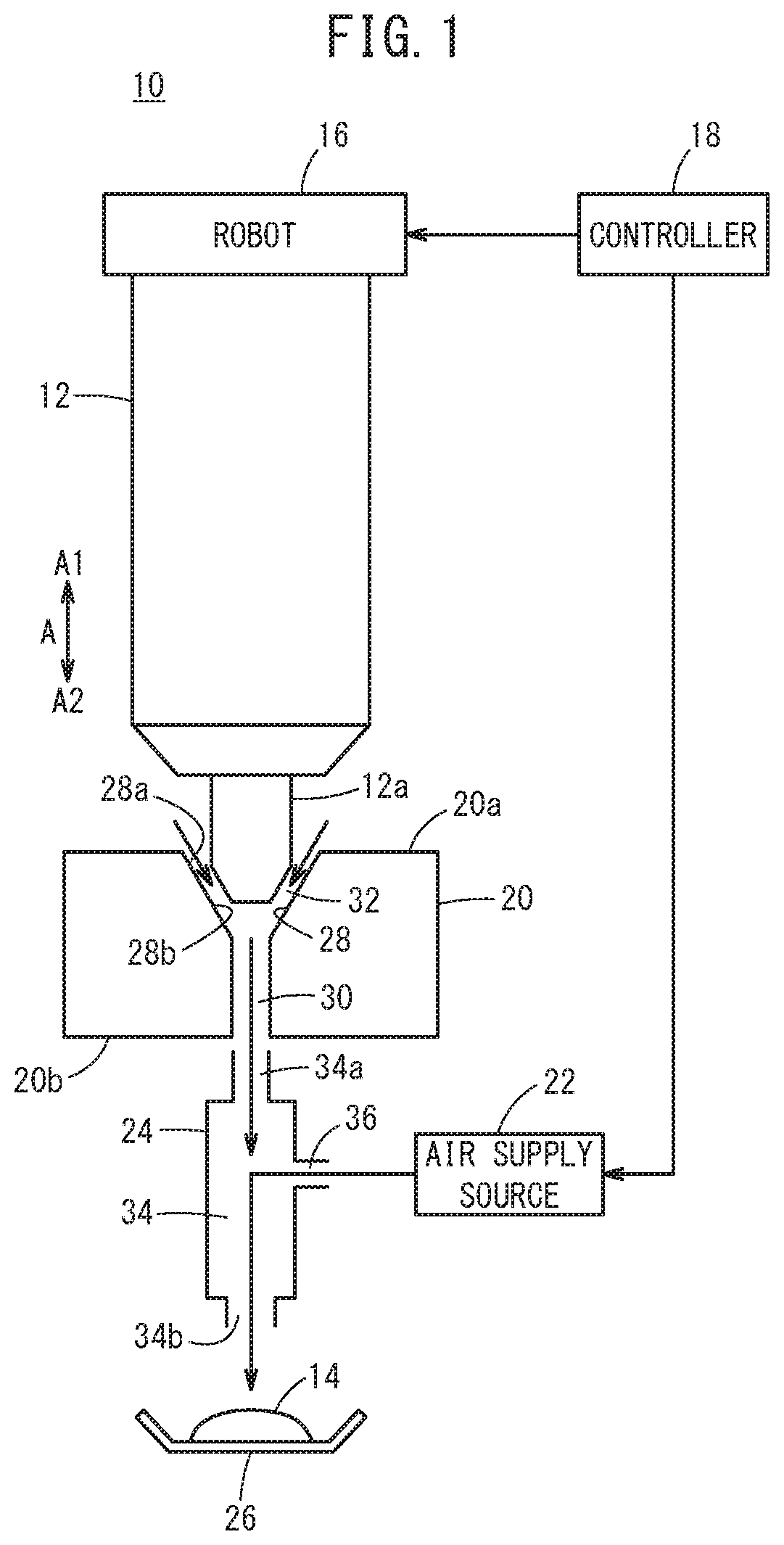
[0060]FIGS. 1-5 have described the case where the tip section 12a of the nozzle 12 is inserted into the tapered section 28 by operating the robot 16. The second modified example shows an example where, in the case that the nozzle 12 mounted on the robot 16 is disposed in a fixed position (a position that application work is performed by the nozzle 12), the deposit 14 of the tip section 12a of the nozzle 12 is removed by moving the nozzle deposit removing device 10 and surrounding the tip section 12a of the nozzle 12 by the tapered section 28. FIG. 6 illustrates the case where the nozzle 12 is disposed substantially horizontally.

[0061]In the second modified example too, removal work (cleaning work) of the deposit 14 can be performed similarly to in the case of FIGS. 1-5. Now, it should be noted that in the second modified example, the nozzle insertion member 20 and the negative pressure generating unit 24 are disposed in a horizontal direction matching the ...


PUM


Abstract

In a nozzle deposit removing device and a method of nozzle deposit removal, compressed air is supplied to an air supply hole of a negative pressure generating unit from an air supply source, and compressed air is released to outside via an other end of a release hole from the air supply hole, thereby generating a flow of negative pressure directed from a tapered section of a nozzle insertion member toward the release hole via a through-hole. Next, a tip section of the nozzle is inserted into the tapered section of the nozzle insertion member, thereby forming a gap between the tapered section communicating with the through-hole and the tip section of the nozzle.

Description

CROSS-REFERENCE TO RELATED APPLICATION[0001]This application is based upon and claims the benefit of priority from Japanese Patent Application No. 2019-012731 filed on Jan. 29, 2019, the contents of which are incorporated herein by reference.BACKGROUND OF THE INVENTIONField of the Invention[0002]The present invention relates to a nozzle deposit removing device and a method of nozzle deposit removal for removing a deposit that has attached to a nozzle.Description of the Related Art[0003]In Japanese Laid-Open Patent Publication No. 2007-216191, for example, it is disclosed with regards to a nozzle for jetting a viscous liquid application material, that after use of the nozzle, a tip of the nozzle is inserted into an inverse conically shaped tapered section formed in a block, and compressed air is blown toward the tip of the nozzle, whereby the application material that has attached to the nozzle is blown off.SUMMARY OF THE INVENTION[0004]However, in the case where a gap between the no...

Claims


Application Information

Patent Timeline
IPC IPC(8): B05B15/50
CPCB05B15/50B08B5/04B05B15/522B05B15/55B05B15/555
Inventor ODA, KOJI
Owner HONDA MOTOR CO LTD
Why Eureka
Try Eureka