Pressurizing shower head

A shower and negative pressure technology, applied in the field of sanitary ware, can solve problems such as waste of water resources and affect the user experience of products, achieve the effects of reducing production costs, avoiding waste of water resources, and improving market competitiveness

Pending Publication Date: 2020-05-26
XIAMEN DELMEI SANITARY WARE
View PDF8 Cites 1 Cited by
  • Summary
  • Abstract
  • Description
  • Claims
  • Application Information

AI Technical Summary

Problems solved by technology

However, there are still some deficiencies in the existing air bubble structure. For example, the water flow will be sprayed outward through the suction hole to cause a waste of water res

Method used


Image

  • Pressurizing shower head
  • Pressurizing shower head
  • Pressurizing shower head

Examples


Embodiment Construction

[0021] The present invention will be further described below in conjunction with the accompanying drawings and specific embodiments.

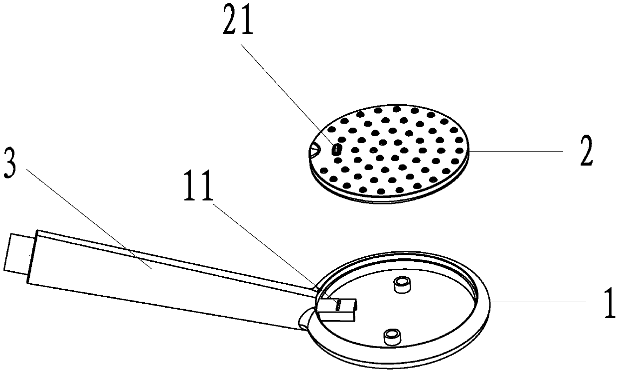
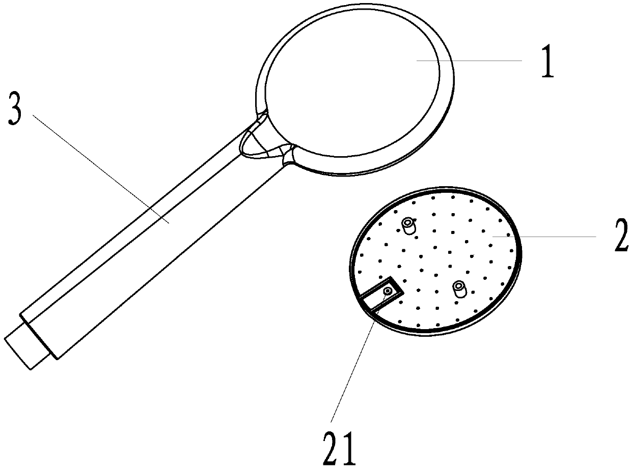
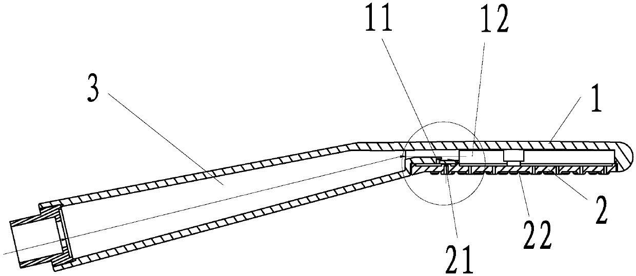
[0022] A pressurized shower, refer to Figures 1 to 5 , comprising an upper cover 1, a lower cover 2, and a handle 3, the upper cover 1 and the handle 3 are integrally formed; the upper cover 1 is fixedly connected to the lower cover 2; the lower cover 2 is close to the The handle 3 is provided with an air inlet 21 along the water outlet direction; the upper cover 1 is provided with a water barrier facing the air inlet 21, and there is a water barrier between the water barrier and the lower cover 2. An air intake chamber 23, the air intake chamber 23 communicates with the air intake hole 21; there is also a negative pressure cavity 24 between the upper cover 1 and the lower cover 2, and the negative pressure cavity 24 communicates with the air intake Cavity 23; the upper cover 1 is provided with an air inlet groove 11 along the water outlet di...


PUM


Abstract

The invention provides a pressurizing shower head. The pressurizing shower head comprises an upper face cover, a lower face cover and a handholding portion, and the upper face cover and the handholding portion are integrally formed; the upper face cover and the lower face cover are fixedly connected; the portion, close to the handholding portion, of the lower face cover is provided with an air inlet hole in the water outlet direction; the portion, directly facing the air inlet hole, of the upper face cover is provided with a water isolating part, an air inlet cavity is formed between the waterisolating part and the lower face cover, and the air inlet cavity communicates with the air inlet hole; a negative-pressure mold cavity is formed between the upper face cover and the lower face coverand communicates with the air inlet cavity; the portion, close to the handholding portion, of the upper face cover is provided with an air inlet groove in the water outlet direction; and the air inlet groove communicates with the negative-pressure mold cavity and a water inlet way. By applying the technical scheme, the purpose of being arranged on the face covers can be achieved, and water flow can be blocked from flowing out from the air inlet hole.

Description

technical field [0001] The invention relates to the field of sanitary ware, in particular to a pressurized shower. Background technique [0002] In the prior art, the air bubble structure of the shower is generally generated by negative pressure when the water flow passes through the mold cavity, and then the air is sucked in by the suction hole, and then the air is mixed with the water flow to form bubble water. However, there are still some deficiencies in the existing air bubble structure. For example, the water flow will be sprayed outward through the suction hole to cause a waste of water resources. In addition, when the shower is turned off, the residual water flows out from the air inlet provided on the handle of the shower, which affects the user experience of the product. Contents of the invention [0003] The purpose of the present invention is to overcome the disadvantages of the above-mentioned prior art, and provide a pressurized shower, which realizes that t...

Claims


Application Information

Patent Timeline
IPC IPC(8): B05B1/18B05B7/04
CPCB05B1/185B05B7/0416
Inventor 倪长征严永强
Owner XIAMEN DELMEI SANITARY WARE
Why Eureka
Try Eureka