Cage type well drilling leakage stopping device and well drilling leakage stopping method

A plugging method and cage technology, applied in the field of oil drilling, can solve the problems of reducing the success rate of plugging, rapid loss of high-density cement slurry, stuck drilling, etc. Guaranteed quality effect

Active Publication Date: 2017-10-13
南充西南石油大学设计研究院有限责任公司
View PDF13 Cites 8 Cited by
  • Summary
  • Abstract
  • Description
  • Claims
  • Application Information

AI Technical Summary

Problems solved by technology

Second, there are leakage channels and a large enough space to accommodate drilling fluid in the formation
However, these lost circulation materials have the following disadvantages: Most of the lost circulation materials are potentially harmful to the production layer
In the cement plugging process, when the cement slurry seals the cracks and karst caves, it is difficult to grasp the initial and final setting time, the construction risk is high, and it is very easy to cause the rapid loss of high-density cement slurry and the rapid solidification of quick-setting cement slurry, resulting in drilling Downhole accidents such as tool solidification and drill sticking have caused great economic losses
Bridging plugging mainly uses various plugging materials to prepare plugging slurry in a certain proportion, and then plugs the cracks and pore channels, and plugs the leaky layer through bridging, supporting, connecting, plugging, filling, etc. The key technology is plugging Whether the particle size distribution in the lost circulation agent matches the diameter of the lost channel. However, in the drilling process, sometimes the fracture width and pore size of the lost formation cannot be accurately grasped, and the formulation of the lost circulation agent cannot be optimized and determined, thus increasing construction costs. Uncertainty, reducing the success rate of plugging

Method used


Image

  • Cage type well drilling leakage stopping device and well drilling leakage stopping method
  • Cage type well drilling leakage stopping device and well drilling leakage stopping method
  • Cage type well drilling leakage stopping device and well drilling leakage stopping method

Examples


Embodiment Construction

[0027] The present invention will be further described below in conjunction with the drawings.

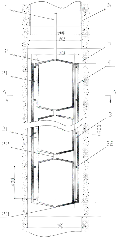
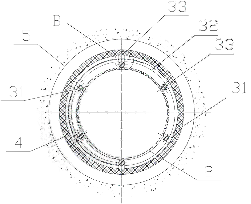
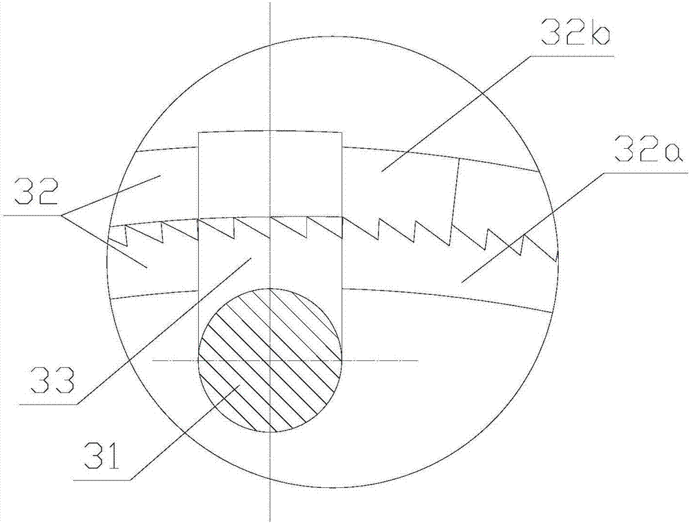
[0028] Such as figure 1 As shown, the cage type drilling leakage plugging device of the present invention includes a small continuous tubing 1, an expansion sleeve 2, a cage 3, and a sealing sleeve 4. The continuous small tubing 1 is connected to the expansion sleeve 2, and the expansion sleeve 2 is in a closed shape and continuously small. The oil pipe 1 can inject air and exhaust gas into the expansion sleeve 2 to realize the expansion and contraction changes of the expansion sleeve 2. The expansion sleeve 2 can be a whole, or as figure 1 As shown, the expansion sleeve 2 is formed by a plurality of identical expansion sub-sleeves 21 in series, and two ends of the expansion sub-sleeve 21 are respectively provided with matching joints to facilitate the series connection as required. The connecting pipe 22 is connected, wherein the expansion sleeve 21 at the head end is connected with ...


PUM


Abstract

The invention discloses a cage type well drilling leakage stopping device and a well drilling leakage stopping method, and relates to the technical field of petroleum drilling. By the cage type well drilling leakage stopping device and the well drilling leakage stopping method, the well drilling leakage stopping success rate can be increased. According to the technical scheme, the cage type well drilling leakage stopping device comprises a continuous small oil tube, an expansion sleeve, a cage and a sealing sleeve, wherein the continuous small oil tube is connected with the expansion sleeve; the cage comprises cage columns and a locking ring; a ratchet, a pawl and a clamp are respectively arranged at two ends of the locking ring; by the ratchet and the pawl, the locking ring only can be expanded; the sealing sleeve sleeves the outer side of the cage; and the expansion sleeve is positioned in the cage. By gas injection expansion of the expansion sleeve, the whole cage is suspended on the continuous small oil tube, and then is downwards fed to a leakage stopping point for well drilling; the expansion sleeve continues being injected with gas, and the cage and the sealing sleeve are locked on a well wall barrel of a repairing and expanding section; after being exhausted, the expansion sleeve is taken out, finally, a leakage section is stopped with cement, and then the cement is solidified; and the leakage stopping point has been improved, so that the leakage stopping success rate is increased.

Description

Technical field [0001] The invention relates to the technical field of petroleum drilling, in particular to a cage-type drilling plugging device and a drilling plugging method. Background technique [0002] In drilling engineering, lost circulation is a phenomenon in which drilling fluid leaks from the wellbore into the formation. Lost circulation often occurs during drilling or tripping, and is a common and frequently encountered complex problem during oil and gas drilling. The downhole accidents caused by lost circulation are complicated and cause great harm to the drilling and completion construction. It has always been a concern of the domestic and foreign petroleum engineering circles. [0003] During drilling operations, once a lost circulation occurs, it will not only delay time, lose drilling fluid, damage oil and gas reservoirs, and interfere with geological logging, but also may cause well wall instability, leading to a series of complex situations such as well collapse,...

Claims


Application Information

Patent Timeline
Patent Type & Authority Applications(China)
IPC IPC(8): E21B33/13
CPCE21B33/13Y02E10/10
Inventor 张泉
Owner 南充西南石油大学设计研究院有限责任公司
Why Eureka
Try Eureka