Airflow horizontal movement type drying room with dehumidification free of influencing airflow circulation

An air circulation and translational technology, applied in the direction of drying, drying machine, drying gas arrangement, etc., can solve the problems of drying room construction, inconvenient use, complex dehumidification system, slow drying of materials, etc., and achieve excellent baking effect , The air circulation channel is spacious, and the effect of drying is uniform

Pending Publication Date: 2017-10-13
张博琳
View PDF7 Cites 3 Cited by
  • Summary
  • Abstract
  • Description
  • Claims
  • Application Information

AI Technical Summary

Problems solved by technology

During the use of this drying room, the temperature in most areas of the baking room is very uniform, and the use effect is very ideal. The fly in the ointment is: the temperature in the middle and lower part of the heating room near the partition wall is somewhat low, resulting in the material in this area drying slightly slower
At the same time, because the dehumidification system of this type of drying room is somewhat complicated, it is inconvenient to construct and use this type of drying room.

Method used


Image

  • Airflow horizontal movement type drying room with dehumidification free of influencing airflow circulation
  • Airflow horizontal movement type drying room with dehumidification free of influencing airflow circulation
  • Airflow horizontal movement type drying room with dehumidification free of influencing airflow circulation

Examples


Embodiment 1

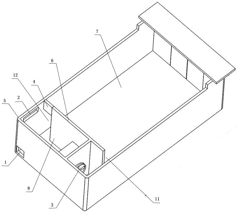
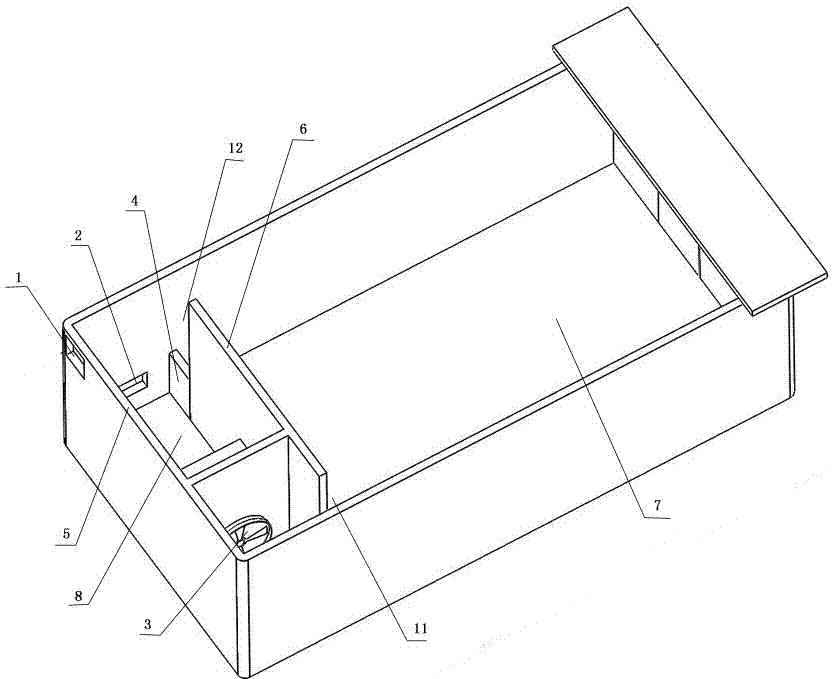
[0023] Such as Figure 1-2 As shown, the present invention discloses an air flow translational single circulation drying room in which the return air blocking area 4 is arranged at the top of the return air outlet 12. The left and right sides of the partition wall 6 between the heating chamber 8 and the material chamber 7 are respectively provided with heating chamber 8 The air inlet 11 for supplying air to the material chamber 7 and the return air outlet 12 for returning air from the material chamber 7 to the heating chamber 8 , the return air blocking area 4 is arranged on the top of the return air outlet 12 . The drying room is provided with an air intake facility and a dehumidification facility. The air intake facility is connected to the air inlet 2 outside the drying room or an air intake fan or a combination of the two. The dehumidification facility is a External dehumidification port 1 or dehumidification fan or a combination of the two, the air inlet 2 is set on the s...

Embodiment 2

[0029] Such as image 3 As shown, the present invention discloses an airflow translational single-circulation drying room in which the return air blocking area 4 is arranged in the middle of the return air outlet 12. The left and right sides of the partition wall 6 between the heating chamber 8 and the material chamber 7 are respectively provided with a heating chamber 8 The air inlet 11 that supplies air to the material chamber 7 and the air return port 12 that returns air from the material chamber 7 to the heating chamber 8, the return air blocking area 4 is located in the middle of the return air port 12, and the return air port 12 is located at the end of the return air blocking area 4 Up and down sides. The drying room is provided with an air intake facility and a dehumidification facility. The air intake facility is connected to the air inlet 2 outside the drying room or an air intake fan or a combination of the two. The dehumidification facility is a External dehumidif...

Embodiment 3

[0032] Such as Figure 4 As shown, the present invention discloses an air flow translational single-circulation drying room in which the return air blocking area 4 is arranged at the lower end of the return air outlet 12. The left and right sides of the partition wall 6 between the heating chamber 8 and the material chamber 7 are respectively provided with a heating chamber 8 The air inlet 11 for supplying air to the material chamber 7 and the air return port 12 for returning air from the material chamber 7 to the heating chamber 8, the air return blocking area 4 is arranged at the bottom of the air return port 12 .

[0033] The drying room is provided with an air intake facility and a dehumidification facility. The air intake facility is connected to the air inlet 2 outside the drying room or an air intake fan or a combination of the two. The dehumidification facility is a External dehumidification port 1 or dehumidification fan or a combination of the two, the air inlet 2 is...


PUM


Abstract

The invention discloses an airflow horizontal movement type drying room with dehumidification free of influencing airflow circulation. The airflow horizontal movement type drying room with dehumidification free of influencing airflow circulation comprises a heating chamber and a material chamber. A return air opening is provided with an air return stopping area. The drying room is provided with an air intake facility and a dehumidification facility. The air intake facility is an air inlet communicating with the outside of the drying room or an air intake draught fan or the combination of the air inlet and the air intake draught fan. The dehumidification facility is a dehumidification opening leading to the outside of the drying room or a dehumidification draught fan or the combination of the dehumidification opening and the dehumidification draught fan. The air inlet is arranged in the heating chamber and located on the portion, in the area between an upper edge and a lower edge of the air return stopping area, of an outer wall. The dehumidification opening is arranged in the heating chamber and located on the portion, between the upper edge and the lower edge of the air return opening, of the outer wall. According to the airflow horizontal movement type drying room with dehumidification free of influencing airflow circulation, the manner that an obstacle is arranged on an airflow circulation passageway is adopted, a high negative pressure is generated on the area behind the obstacle, and therefore more areas in the drying room are at positive pressure; and in this way, the dehumidification opening can be directly arranged on the outer wall, and dehumidification can be still smoothly conducted.

Description

technical field [0001] The invention belongs to the technical field of an airflow translational drying room, and in particular relates to an airflow translational drying room in which the airflow circulation is not affected by dehumidification. Background technique [0002] Two invention patents with patent numbers ZL201420680631.8 and ZL201420747478.6 disclose two kinds of airflow translational drying rooms. This type of airflow translational drying room sets the air inlet on the side wall of the return air passage area in the heating chamber. The moisture outlet is arranged on the upper and lower sides or one side of the return air outlet, and the moisture outlet will discharge the moisture through the heating chamber to the outside of the drying room through the moisture outlet channel. During the use of this drying room, the temperature in most areas of the baking room is very uniform, and the use effect is very ideal. The fly in the ointment is: the temperature in the m...

Claims


Application Information

Patent Timeline
Patent Type & Authority Applications(China)
IPC IPC(8): F26B9/06F26B21/04F26B23/00F26B25/00
CPCF26B9/06F26B21/04F26B23/00F26B25/00
Inventor 张博琳张中伟
Owner 张博琳
Why Eureka
Try Eureka