Pressure induction device of hydraulic prop

A technology of induction device and hydraulic prop, which is applied in the direction of prop/bracket, mining equipment, earthwork drilling, etc., can solve the problems of unbalanced pressure of hydraulic prop, increase of production expenditure, and affecting the life safety of staff, so as to achieve pressure balance and production The effect of reducing expenses and protecting life safety

Inactive Publication Date: 2017-10-17
XUZHOU ZHONAN SCI & TECH CO LTD
View PDF6 Cites 4 Cited by
  • Summary
  • Abstract
  • Description
  • Claims
  • Application Information

AI Technical Summary

Problems solved by technology

[0002] The criss-cross mine tunnel is the most important item in coal mine safety inspection. In case of an accident, the mine tunnel is the only exit connecting to the outside world. The safety standard of the mine tunnel is also gradually raised. In order to prevent the mine tunnel from collapsing, the most effective The method is to use hydraulic props to support, and this method is generally adopted by coal mining enterprises, but in use, it is found that because the surface of the mine road is uneven, when the hydraulic prop is supporting, the top cover part will withstand the mine road. One part fails to touch the mine road, which will make the pressure of the hydraulic prop unbalanced, and the service life of the hydraulic prop will be greatly shortened for a long time. If the mine collapses, the hydraulic prop will not play any role, which will seriously affect the work The life safety of personnel, in order to solve this phenomenon, the number of hydraulic props used by coal mining enterprises in mine tunnels has increased by two to three times, production expenses have also greatly increased, and the area of ​​mine tunnels has also been greatly reduced, which seriously affects the entry and exit of staff. It is urgent to solve this problem

Method used


Image

  • Pressure induction device of hydraulic prop
  • Pressure induction device of hydraulic prop
  • Pressure induction device of hydraulic prop

Examples


Embodiment Construction

[0017] The present invention will be further described below in conjunction with the accompanying drawings.

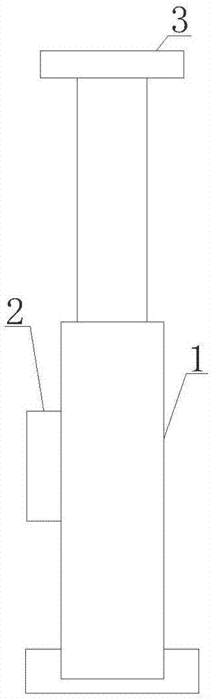
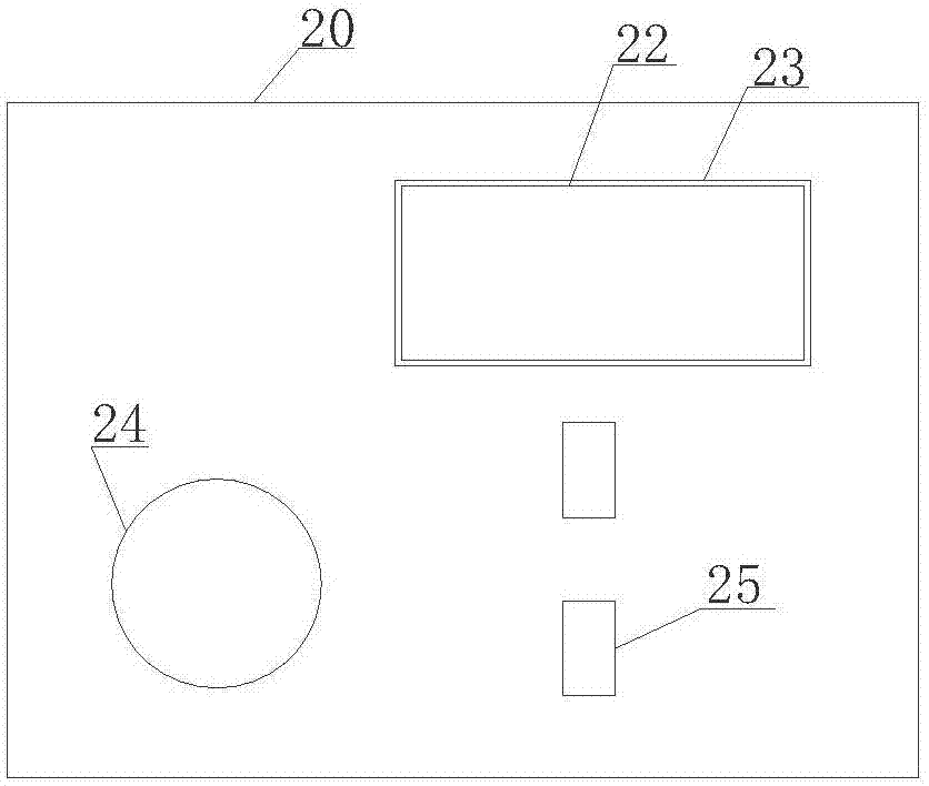
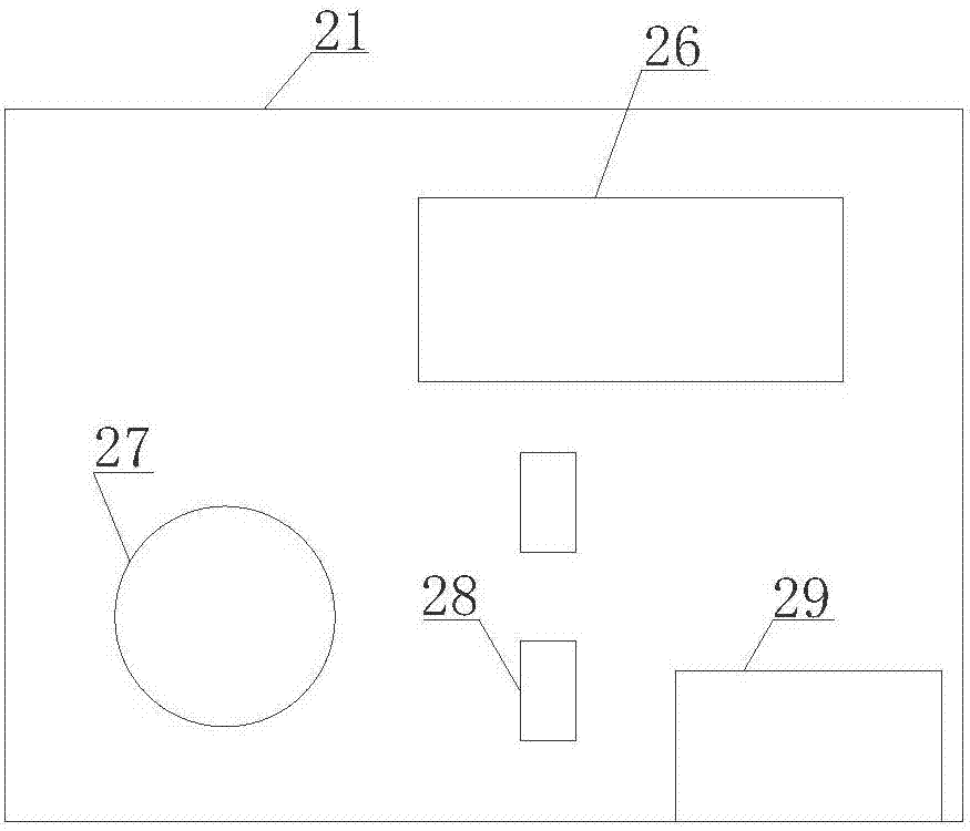
[0018] Such as Figure 1 to Figure 6 As shown, the pressure sensing device of the hydraulic prop is composed of a column body 1, a master control device 2, and a top cover device 3. The top cover device 3 is installed at one end of the column body 1, and the master control device 2 is fixedly installed on the On the cylinder 1; the master control device 2 is composed of the shell I20, the shell II21, the protective cover 22, the through hole I23, the through hole II24, the through hole III25, the display screen 26, the key I27, the key II28 and the control center 29. The shell I20 It is snapped together with the casing II21 to form the casing of the master control device 2. The surface of the casing I20 has through holes I23, through holes II24 and through holes III25. The protective cover 22 is embedded in the through holes I23. The display screen 26, buttons I27, II...


PUM


Abstract

The invention relates to a pressure induction device of a hydraulic prop, and belongs to the technical field of single hydraulic props. The pressure induction device is composed of a prop body, a general control device and a top cover device. The top cover device is installed at one end of the prop body, the general control device is fixedly installed on the prop body, and the general control device is composed of a first outer shell, a second outer shell, a protective cover, a first through hole, a second through hole, a third through hole, a display screen, a first key, a second key and a control center; the top cover device is composed of pressure sensors, a protective shell, a receiver and a transmitter, at least two pressure sensors are installed on the surface of the protective shell, and the pressure sensors are connected with the receiver through electric wires; and the receiver is connected with the transmitter through an electric wire, and the receiver and the transmitter are fixed in the protective shell. The situation that the hydraulic prop cannot be in contact with a tunnel cannot happen, the service life of the hydraulic prop cannot be influenced, and the life safety of workers is guaranteed; and the production expenses cannot be increased, and the usable area of the tunnel cannot be influenced.

Description

technical field [0001] The invention relates to a pressure sensing device, in particular to a pressure sensing device of a hydraulic prop, belonging to the technical field of a single hydraulic prop. Background technique [0002] The criss-cross mine tunnel is the most important item in coal mine safety inspection. In case of an accident, the mine tunnel is the only exit connecting to the outside world. The safety standard of the mine tunnel is also gradually raised. In order to prevent the mine tunnel from collapsing, the most effective The method is to use hydraulic props to support, and this method is generally adopted by coal mining enterprises, but in use, it is found that because the surface of the mine road is uneven, when the hydraulic prop is supporting, the top cover part will withstand the mine road. One part fails to touch the mine road, which will make the pressure of the hydraulic prop unbalanced, and the service life of the hydraulic prop will be greatly short...

Claims


Application Information

Patent Timeline
Patent Type & Authority Applications(China)
IPC IPC(8): E21D15/46E21D15/44
CPCE21D15/46E21D15/44
Inventor 陈亚东曹彦吉华红飞
Owner XUZHOU ZHONAN SCI & TECH CO LTD
Why Eureka
Try Eureka