
Heat radiation structure of LED lamp

A technology of LED lamps and heat dissipation structure, which is applied to the cooling/heating device of lighting devices, lampshades, lighting and heating equipment, etc., which can solve the problems of LED chip failure, restricting the service life of LED lamps, and reducing the luminous efficiency of lamps. Simplicity and the effect of improving heat dissipation efficiency

Inactive Publication Date: 2017-10-17
DONGGUAN LIANZHOU INTPROP OPERATION MANAGEMENT CO LTD
View PDF0 Cites 3 Cited by
  • Summary
  • Abstract
  • Description
  • Claims
  • Application Information

AI Technical Summary

Problems solved by technology

However, during the use of LED lamps, the heat dissipation problem of LED lamps, that is, LED light decay, has become a key factor restricting the service life of LED lamps and the promotion and application of LEDs.
Especially in high-power LED lamps, only 15% to 20% of the input power is converted into light energy output, and the rest is converted into heat energy. If the heat is not discharged to the outside in a timely manner, it will not only reduce the luminous efficiency of the lamp, And it may cause the LED chip to fail rapidly due to excessive temperature

Method used


Image

  • Heat radiation structure of LED lamp
  • Heat radiation structure of LED lamp
  • Heat radiation structure of LED lamp

Examples


Embodiment Construction

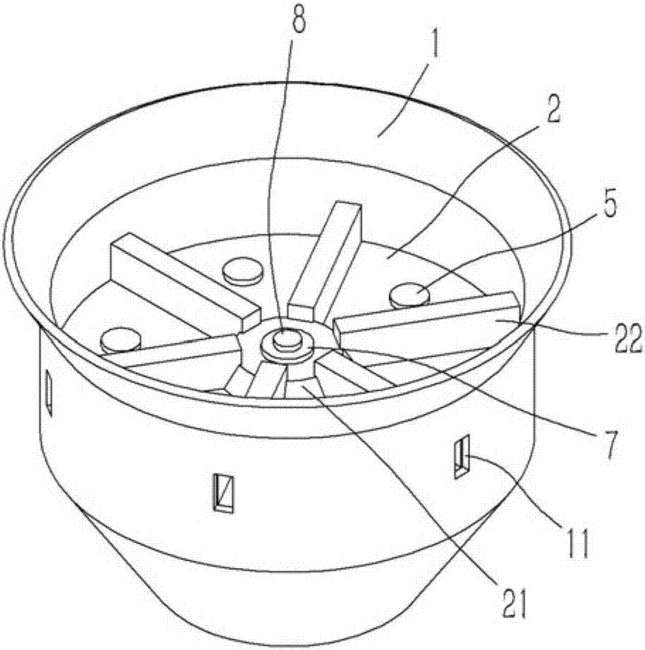
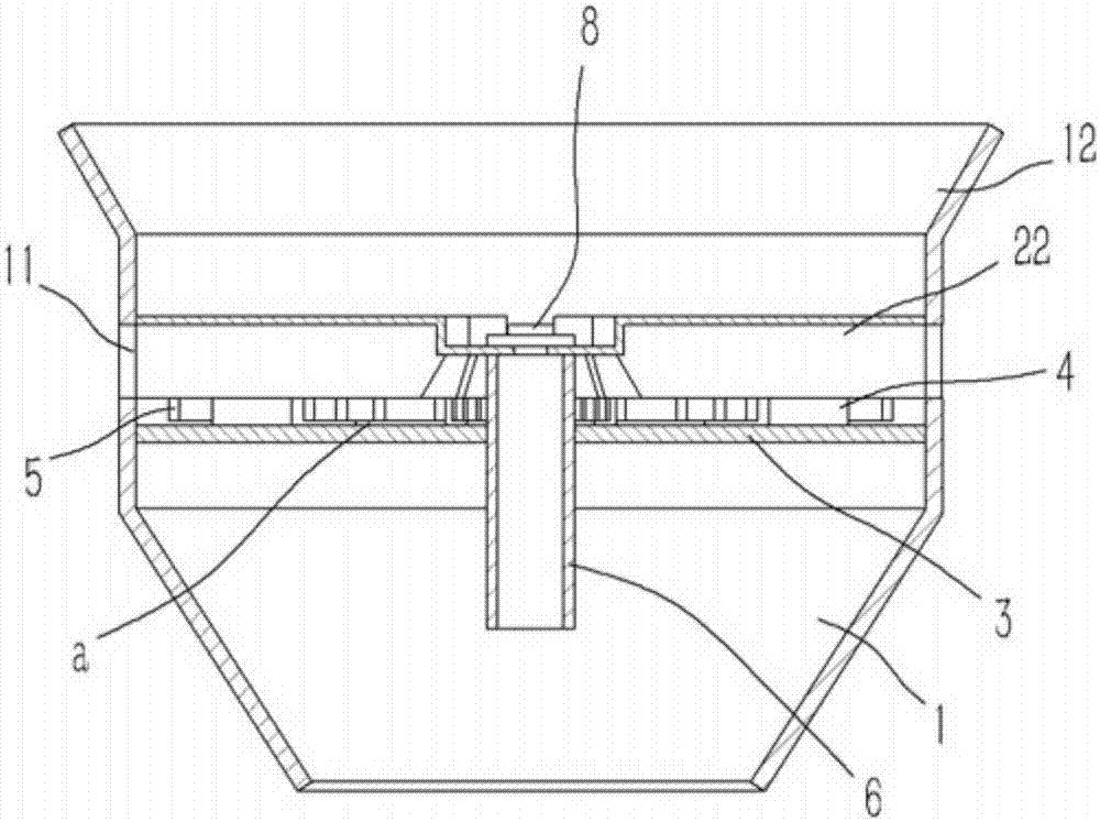
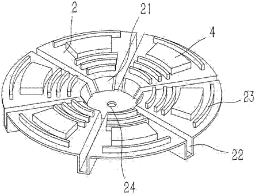
[0017] Example: see Figures 1 to 3 As shown, a heat dissipation structure of an LED lamp includes a lampshade 1 of the LED lamp. A heat dissipation aluminum plate 2 is inserted into the lampshade 1. The middle part of the heat dissipation aluminum plate 2 is stamped and formed with an upwardly protruding round platform 21. The heat dissipation aluminum plate 2 around the round platform 21 is There are several upwardly protruding cooling passages 22 formed by the upper stamping. The cooling passages 22 communicate with the inner cavity of the round table 21. The side wall of the lampshade 1 is formed with a cooling hole 11 communicating with the cooling passages 22 on the heat dissipation aluminum plate 2. The bottom surface of the heat dissipation aluminum plate 2 adjacent to the heat dissipation channel 22 is against the spacer 4, the screw 5 passes through the heat dissipation aluminum plate 2 and is screwed on the spacer 4, the spacer 4 is fixed on the baffle 3, and the baf...


PUM


Abstract

The invention discloses a heat dissipation structure of an LED lamp, which comprises a lampshade of the LED lamp. A heat dissipation aluminum plate is plugged into the lampshade. The middle part of the heat dissipation aluminum plate is punched and formed with an upwardly protruding round platform. The heat dissipation aluminum plate around the round platform is stamped and formed with several lines The upwardly protruding heat dissipation channel communicates with the inner cavity of the round platform. The side wall of the lampshade is formed with a heat dissipation hole that communicates with the heat dissipation channel on the heat dissipation aluminum plate. The bottom surface of the heat dissipation aluminum plate between adjacent heat dissipation channels is against a pad The screw passes through the heat-dissipating aluminum plate and is screwed on the pad, the pad is fixed on the baffle, the baffle is plugged and fixed in the lampshade, a conduit is inserted on the baffle, and the upper end of the conduit is fixed on the bottom surface of the round table On the top, the round table is formed with wire via holes, the top surface of the round table is fixed with a PCB board, and the LED lamp chip is fixed on the PCB board. The invention only optimizes and improves the heat dissipation structure of the LED lamp, and improves the heat dissipation efficiency of the LED lamp without changing the size of the LED lamp.

Description

Technical field: [0001] The present invention relates to the technical field of LED lamps, and more specifically relates to a heat dissipation structure of LED lamps. Background technique: [0002] Due to the characteristics of flexible shape, high brightness, energy saving, environmental friendliness and wide application range, LED lamps occupy an increasing market share in the lighting market. However, during the use of LED lamps, the heat dissipation problem of LED lamps, that is, LED light decay, has become a key factor restricting the service life of LED lamps and the promotion and application of LEDs. Especially in high-power LED lamps, only 15% to 20% of the input power is converted into light energy output, and the rest is converted into heat energy. If the heat is not discharged to the outside in a timely manner, it will not only reduce the luminous efficiency of the lamp, And it may cause the LED chip to fail rapidly due to excessive temperature. [0003] At pres...

Claims


Application Information

Patent Timeline
IPC IPC(8): F21V29/89F21V29/83F21V17/12F21V19/00F21V29/74F21V3/04F21Y115/10
CPCF21V29/89F21V17/12F21V19/001F21V29/74F21V29/83F21Y2115/10
Inventor 徐亚维
Owner DONGGUAN LIANZHOU INTPROP OPERATION MANAGEMENT CO LTD
Learn More