Check patentability & draft patents in minutes with Patsnap Eureka AI!

Rotating speed measuring circuit for measuring magnetic rotating speed sensor signals

A technology of speed sensor and speed measurement, which is applied in the direction of devices using electric/magnetic methods, can solve the problems of square wave loss of speed signal and other problems, and achieve the effect of accurate signal

Inactive Publication Date: 2017-10-17
SICHUAN XINCHUAN AVIATION INSTR
View PDF11 Cites 4 Cited by
  • Summary
  • Abstract
  • Description
  • Claims
  • Application Information

AI Technical Summary

Problems solved by technology

[0005] The technical problem to be solved by the present invention is that the square wave of the rotational speed signal collected by the existing rotational speed measurement circuit will lose its waveform. There will be wave loss, and there will be no jumps and inaccuracies in the speed signal, and the collected signal will be more accurate

Method used


Image

  • Rotating speed measuring circuit for measuring magnetic rotating speed sensor signals

Examples


Embodiment

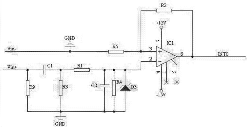
[0018] Such as figure 1 As shown, the present invention discloses a speed measuring circuit for measuring the signal of a magnetic speed sensor, including a band-pass filter circuit, an operational amplifier A, a resistor R2 and a resistor R5, and the input end of the band-pass filter circuit is connected to the positive terminal Vin+ of the speed input signal. , the output terminal of the band-pass filter circuit is connected to the negative input terminal 2 of the operational amplifier A, and the positive input terminal 3 of the operational amplifier A is connected to one terminal of the resistor R2 and one terminal of the resistor R5 at the same time, and the other terminal of the resistor R5 is connected to the negative terminal Vin of the speed input signal -, the negative end of the resistor R5 and the speed input signal are both grounded, and the other end of the resistor R2 is connected to the output terminal 6 of the operational amplifier A; port 4 and port 7 of the op...


PUM


Abstract

The invention discloses a rotating speed measuring circuit for measuring magnetic rotating speed sensor signals. The rotating speed measuring circuit includes a band-pass filter circuit, an operational amplifier A, a resistor R2 and a resistor R5, the input end of the band-pass filter circuit is connected with the positive end of the rotating speed input signal, the output end of the band-pass filter circuit is connected with the inverting input end 2 of the operational amplifier A, the positive input end 3 of the operational amplifier A is connected with one end of the resistor R2 and one end of the resistor R5 at the same time, the other end of the resistor R5 is connected with the negative end of the rotating speed input signal, the resistor R5 and the negative end of the rotating speed input signal are grounded, the other end of the resistor R2 is connected with the output end 6 of the operational amplifier A, and the port 4 and the port 7 of the operational amplifier A are successively connected with a negative power supply and a positive power supply. According to the invention, the rotating speed square wave can be prevented from the wave lost phenomenon, and the phenomena of rotating speed jumping and inaccuracy can be prevented, and the acquired signal is more accurate.

Description

technical field [0001] The invention relates to a magnetic rotational speed sensor, in particular to a rotational speed measuring circuit for measuring signals of the magnetic rotational speed sensor. Background technique [0002] The magnetoelectric speed sensor uses the principle of electromagnetic induction, and is generally used to sense the speed of the corresponding gear and provide an output signal for the speed. The permanent magnet, coil and shell of the sensor are all fixed, and the gear is installed on the measured rotating shaft. When the gear rotates, the magnetic flux passing through the sensor changes, and an electric potential is induced in the coil. The frequency f (Hz) depends on the number of teeth The product of N and speed n(r / min), that is After amplification and shaping, the regular pulse signal is output, and this signal is input into the frequency acquisition circuit, and the rotational speed can be calculated from the frequency. [0003] In the p...

Claims


Application Information

Patent Timeline
IPC IPC(8): G01P3/50
CPCG01P3/50
Inventor 赵宝康林翔
Owner SICHUAN XINCHUAN AVIATION INSTR
Features
  • R&D
  • Intellectual Property
  • Life Sciences
  • Materials
  • Tech Scout
  • Unparalleled Data Quality
  • Higher Quality Content
  • 60% Fewer Hallucinations
Learn More