Feeding type cylinder side edge strip wing drilling fixture

A technology of drilling fixtures and side strips, which is applied in the direction of drilling/drilling equipment, manufacturing tools, and drilling molds for workpieces, etc., which can solve the problems of inability to process, long time consumption, and long processing cycle, etc., to achieve Ensure the assembly requirements, improve work efficiency, and improve the effect of machining accuracy

Inactive Publication Date: 2017-10-20
SICHUAN AEROSPACE LONG MARCH EQUIP MFG CO LTD
View PDF5 Cites 4 Cited by
  • Summary
  • Abstract
  • Description
  • Claims
  • Application Information

AI Technical Summary

Problems solved by technology

[0002] When processing the holes on the four side strips of a cylindrical product, it is generally processed by drilling machine after scribing or machining by machining center. If the drilling machine is used for processing after scribing, a scribing process needs to be added. After scribing, it is necessary to use a sample punch to punch out the center of the hole. Due to manual errors during scribing and punching, the position deviation is relatively large. The hole is tilted, and the processing cycle of this method is longer; while the processing with a machining center has higher precision, but it needs to occupy the machining center equipment to process a product, and it takes a long time to clamp and disassemble the product. The center cannot process other complex products; in addition, due to the high man-hours of the machining center, the processing cost of the holes on the side strips is relatively high

Method used


Image

  • Feeding type cylinder side edge strip wing drilling fixture
  • Feeding type cylinder side edge strip wing drilling fixture
  • Feeding type cylinder side edge strip wing drilling fixture

Examples


Embodiment

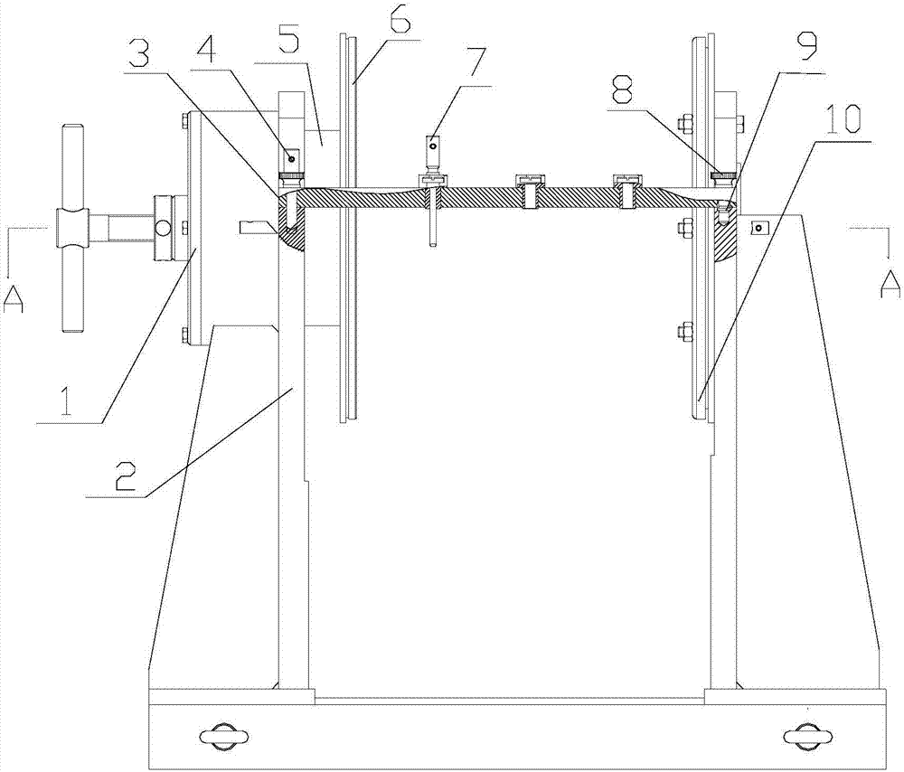
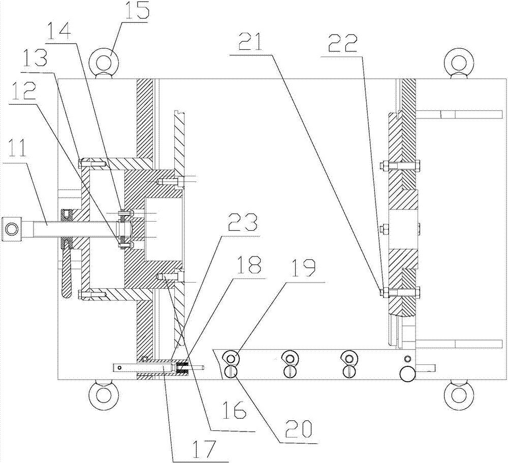
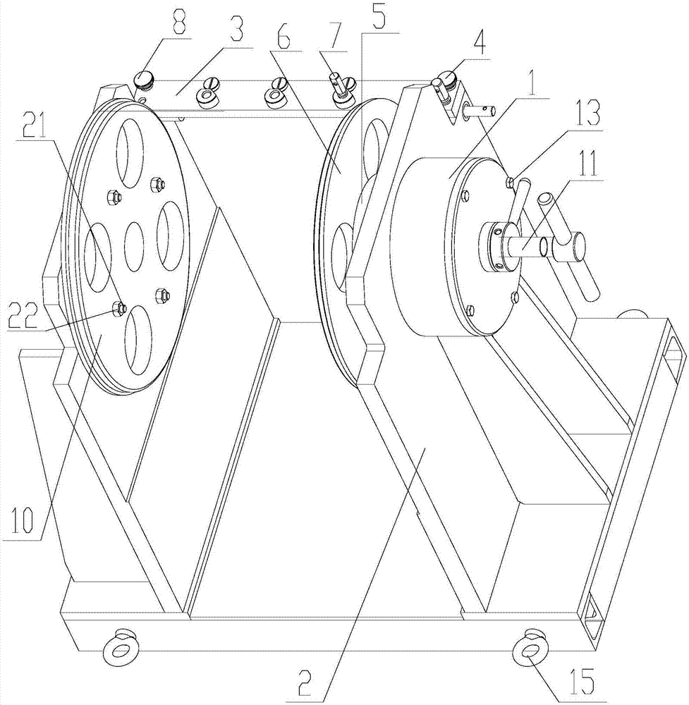
[0022] A kind of feed type cylinder side strip wing drilling jig, see Figure 1-7 , including clamp body 2, drill template 3, rotating shaft 5, adjustable positioning plate 6, blocking cover 1, pressure plate 10, limit block 14, compression screw 11, knurled high-head screw 8, positioning pin a4, positioning pin b7, quick change drill sleeve 19, bolt washer assembly 12 and other parts, specifically:

[0023] The clamp body 2 is welded by steel plate 1-1, left support 1-2, right support 1-3, and base 1-4, and the base 1-4 is welded by channel steel, and the overall aging after welding is as required Processed in place, four lifting ring screws 15 are installed on both sides of the base 1-4 of the clamp body 2, which are used for lifting the whole feed type cylinder side strip wing drilling jig, the clamp body 2 is the main body of the present invention, and all the other parts are installed on the clamp body 2 to form a whole;

[0024] The blocking cover 1 is connected with t...


PUM

PropertyMeasurementUnit
diameteraaaaaaaaaa
lengthaaaaaaaaaa

Abstract

The invention discloses a feeding type cylinder side edge strip wing drilling fixture, and belongs to the field of fixtures. The drilling fixture comprises parts such as a fixture body, a drilling jig plate, a rotation shaft, an adjustable positioning plate, a blanking cap, a pressing disc, a limiting block, a compression screw, a knurled thumb screw, a positioning plug pin a, a positioning plug pin b, quick-changing drilling bushings and a bolt washer assembly. By adopting the drilling fixture, the hole machining precision can be greatly improved, the assembling requirement of a corresponding product is guaranteed, occupation of a machining center can be reduced, the machining cost is reduced, and the working efficiency is improved. Through actual detection, when drilling and reaming machining is conducted on sixteen holes formed in four side edge strip wings of a cylindrical product with the diameter of 400 mm and the length of 500 mm by adopting the drilling fixture, the position degree can meet the requirement of 0.1 mm.

Description

technical field [0001] The invention relates to a drilling jig, in particular to a feed type cylinder side strip wing drilling jig. Background technique [0002] When processing the holes on the four side strips of a cylindrical product, it is generally processed by drilling machine after scribing or machining by machining center. If the drilling machine is used for processing after scribing, a scribing process needs to be added. After scribing, it is necessary to use a sample punch to punch out the center of the hole. Due to manual errors during scribing and punching, the position deviation is relatively large. The hole is tilted, and the processing cycle of this method is longer; while the processing with a machining center has higher precision, but it needs to occupy the machining center equipment to process a product, and it takes a long time to clamp and disassemble the product. The center cannot process other complex products; in addition, due to the high man-hours of...

Claims


Application Information

Patent Timeline
Patent Type & Authority Applications(China)
IPC IPC(8): B23B47/28B23B49/02
CPCB23B47/281B23B49/02B23B2247/12
Inventor 刘何荣龙飞王彬许宝文
Owner SICHUAN AEROSPACE LONG MARCH EQUIP MFG CO LTD
Why Eureka
Try Eureka