Engine piston pin clamp spring press-fitting equipment

A technology of piston pin and engine, applied in metal processing equipment, transportation and packaging, metal processing, etc., can solve problems such as circlip stagnation

Pending Publication Date: 2017-10-20
SAIC-GM-WULING AUTOMOBILE CO LTD
View PDF0 Cites 2 Cited by
  • Summary
  • Abstract
  • Description
  • Claims
  • Application Information

AI Technical Summary

Problems solved by technology

[0008] The invention provides an engine piston pin circlip pressing device, which aims to solve th

Method used


Image

  • Engine piston pin clamp spring press-fitting equipment
  • Engine piston pin clamp spring press-fitting equipment
  • Engine piston pin clamp spring press-fitting equipment

Examples


Embodiment 1

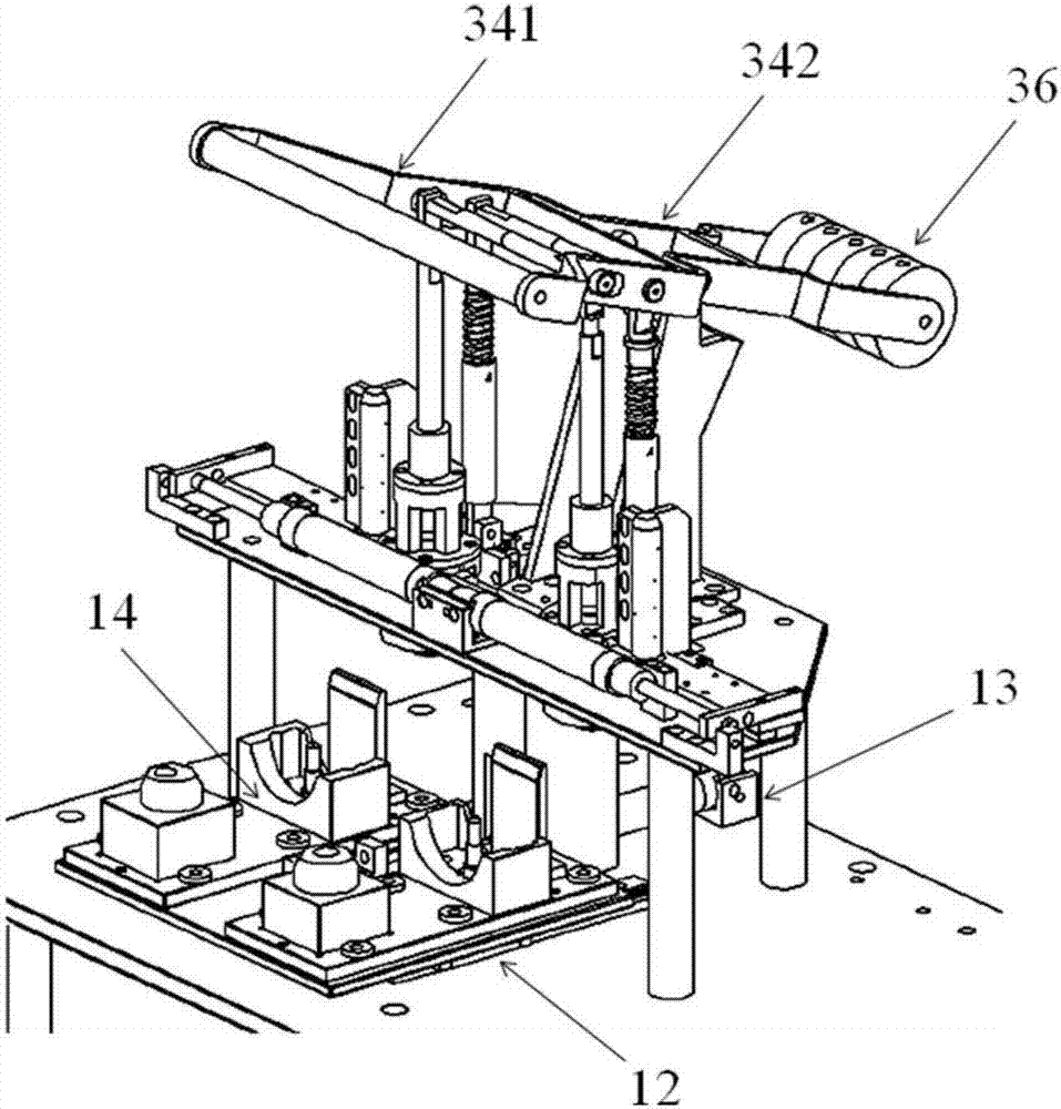
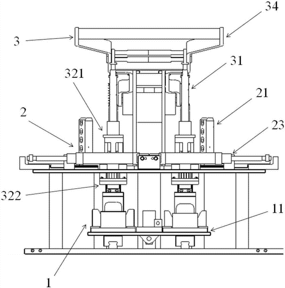
[0029] Such as Figure 1 to Figure 4 As shown, the engine piston pin circlip pressing equipment includes a piston feeding mechanism 1, a circlip feeding mechanism 2, and a pressing mechanism 3. The pressing mechanism 3 includes a pressure rod 31, a pressure head 32, a pressure head end cover 33, and 32 is composed of an upper pressing head 321 and a lower pressing head 322. The pressing head 32 is a through-hole structure as a whole, the pressing rod 31 moves in the through hole, the upper pressing head 321 is fixedly connected, and the lower pressing head 322 and the upper pressing head 321 are connected in cross contact , the lower pressure head 322 slides up and down relative to the upper pressure head 321, the pressure head end cover 33 is arranged on the upper end of the upper pressure head 32, and the circlip feeding mechanism 2 moves to the pressure head end cover 33 and the upper pressure head 321 when the circlip feeds. In the formed feeding chamber, the lower pressin...

Embodiment 2

[0034] Such as Figures 5 to 7 As shown, the circlip feeding mechanism 2 includes a circlip material column 21, a push pedal 22, and a push pedal cylinder 23. The push pedal 22 is composed of a push pedal front end 221 and a push pedal rear end 222, and the height of the push pedal front end 221 is low. At the height of the push pedal rear end 222, the push pedal front end 221 is connected to the push pedal rear end 222 in a step shape, the push pedal cylinder 23 is connected to the push pedal rear end 222, and the spring material column 21 is connected to the push pedal front end. 221 contact connections.

[0035] Wherein, the height difference between the front end portion 221 of the push plate and the rear end portion 222 of the push plate is equal to or smaller than the thickness of the retaining spring 5 .

[0036] A spring hole 24 is provided at the joint between the front end portion 221 of the push plate and the rear end portion 222 of the push plate, and the spring h...

Embodiment 3

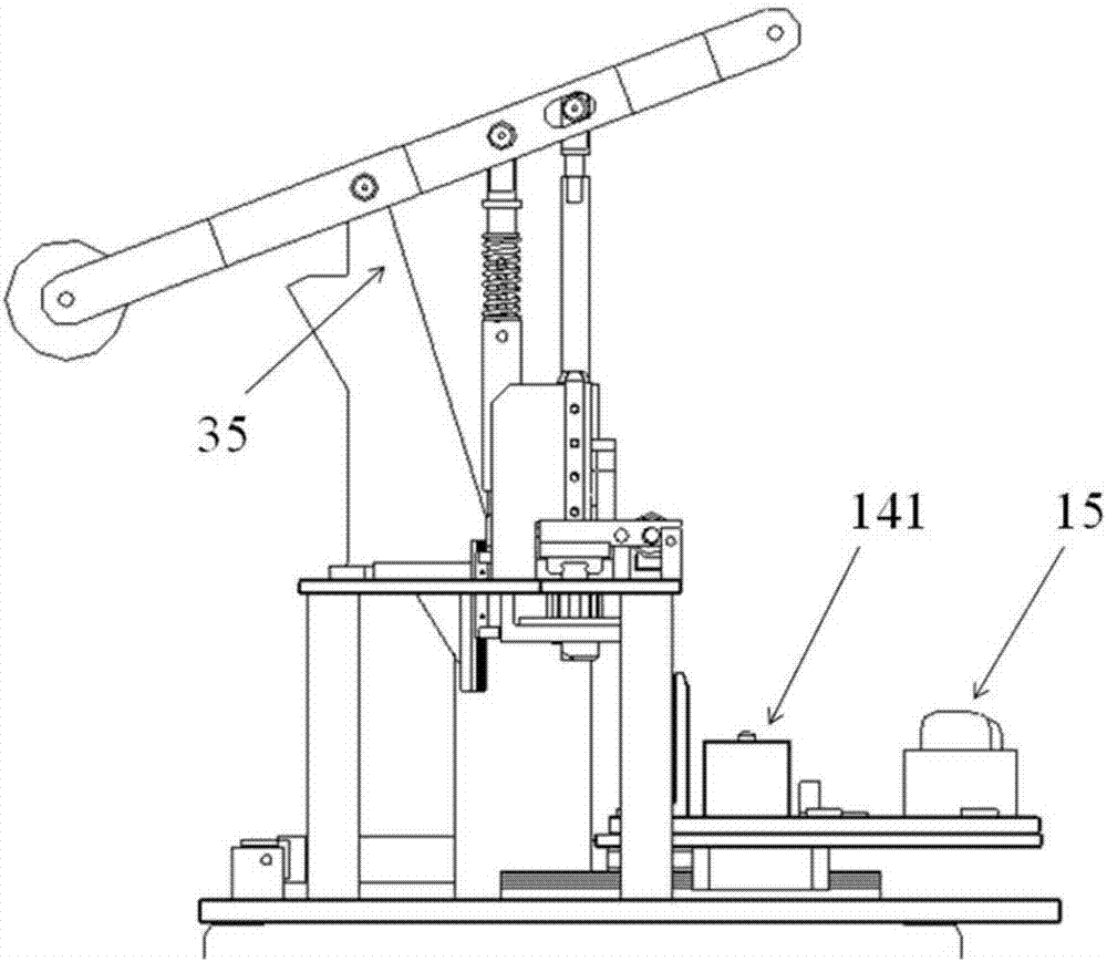
[0039] Such as Figures 1 to 4 As shown, the press-fit mechanism 3 includes a handle 34, a handle fixing rod 35, one end of the handle fixing rod 35 is hinged with the middle part of the handle 34, and the other end is fixedly connected, the handle 34 is divided into a handle pressing part 341 and a handle counterweight part 342, with The connection between the handle fixing rod 35 and the handle 34 is a boundary, and the distance between the handle pressing part 341 and the connecting part is smaller than the distance between the handle weight part 342 and the connecting part. The pressing rod 31 moves up and down in the through hole of the pressing head 32 . The press-fitting mechanism 3 also includes a counterweight 36 connected to the counterweight part 342 of the handle.

[0040] The circlip feeding mechanism 1 is driven by a cylinder to ensure the stable positioning of the feeding mechanism. When the clip spring feeds, it directly falls on the push plate to move, and t...


PUM


Abstract

The invention relates to an engine piston pin circlip pressing device. The equipment includes a piston feeding mechanism, a spring feeding mechanism, and a pressing mechanism. The pressing mechanism includes a pressure rod, a pressure head, and an end cover of the pressure head. The pressure head is composed of an upper pressure head and a lower pressure head. The pressure head is a through-hole structure. , the pressure rod moves in the through hole, the upper pressure head is fixedly connected, the lower pressure head and the upper pressure head are connected in cross contact, the lower pressure head slides up and down relative to the upper pressure head, the pressure head end cover is arranged on the upper end of the upper pressure head, and the clamping The spring feeding mechanism moves into the feeding cavity formed by the pressure head end cover and the upper pressure head when the circlip is feeding, and the lower pressure head is attached to the surface of the piston feeding mechanism when the circlip is pressed. The equipment is driven by compressed air, and the cylinder is used to drive the piston and the piston circlip feeding mechanism for feeding, so as to ensure the stable operation of the feeding mechanism. The circlip pressing part is driven by manpower for pressing, and the pressing handle is equipped with a counterweight to provide sufficient pressing force for the pressing, and the operator only needs a small force to perform the pressing operation.

Description

technical field [0001] The invention relates to an automobile press-fitting tool, in particular to a press-fitting device for an engine piston pin circlip. Background technique [0002] The circlip press-fitting equipment currently used is a simple semi-automatic press-fitting equipment. At the initial stage of the project, the equipment can only press-fit the C14 model, and the B15 model has poor compatibility. Each part of the equipment has a complex structure and high assembly precision. A pusher cylinder simultaneously pushes the piston and the circlip to feed the material. During the feeding process of the circlip, it passes through multiple mechanical parts such as the circlip slideway and the pressure head. The circlip is compressed in the tapered pressure head, and finally the compression is completed. Pack. The mechanical parts of the equipment cooperate with high precision. [0003] Technical flaws: [0004] 1. After the circlip reaches the inside of the pressu...

Claims


Application Information

Patent Timeline
IPC IPC(8): B23P19/02
CPCB23P19/02B23P2700/50
Inventor 杜际山黄永辉许可会张圣峰关晓丽
Owner SAIC-GM-WULING AUTOMOBILE CO LTD
Why Eureka
Try Eureka