Method and device for controlling rotational joints of robot to move and robot

A technology of rotating joints and robots, which is applied in the direction of program-controlled manipulators, manipulators, manufacturing tools, etc. It can solve problems such as affecting accuracy, inaccurate model parameter identification, robot vibration, etc., to achieve improved control performance, good fitting effect, and improved The effect of accuracy

Active Publication Date: 2017-10-20
GUANGZHOU SHIYUAN ELECTRONICS CO LTD
View PDF5 Cites 19 Cited by
  • Summary
  • Abstract
  • Description
  • Claims
  • Application Information

AI Technical Summary

Problems solved by technology

However, the large random error in the measurement during identification will lead to inaccurate identification of model parameters. Therefore, before the overall parameter identification, it is helpful to preliminarily determine the parameters of partial identification, such as the parameters of the friction model. The accuracy of parameter identification, especially in the low-speed stage, the main driving torque of the robot's drive motor is used to offset the friction torque of the joint, so before performing the parameter identification of the robot dynamic model, first identify the friction model parameters of the joint separately , which is very helpful to improve the accuracy of identification
Generally, when identifying the friction model parameters of the joints, the curve of the position of the triangular waveform versus time is used to make the robot run at a constant speed, but the curve of the variation of the position of the triangle waveform over time is a pulse waveform, then When the robot moves, it will cause the vibration of the robot, which will further affect the result of the measured friction torque, resulting in inaccurate identification of the friction model parameters of the joints, that is, the constructed friction model is inaccurate, which in turn affects the control of the robot to rotate the joints. movement accuracy

Method used


Image

  • Method and device for controlling rotational joints of robot to move and robot
  • Method and device for controlling rotational joints of robot to move and robot
  • Method and device for controlling rotational joints of robot to move and robot

Examples


Embodiment Construction

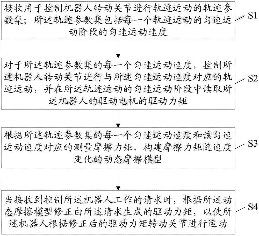
[0045] The following will clearly and completely describe the technical solutions in the embodiments of the present invention with reference to the accompanying drawings in the embodiments of the present invention. Obviously, the described embodiments are only some, not all, embodiments of the present invention. Based on the embodiments of the present invention, all other embodiments obtained by persons of ordinary skill in the art without creative efforts fall within the protection scope of the present invention.

[0046] The model used in the embodiment of the present invention to describe the friction moment of the robot when the rotating joint is moving is the LuGre friction model, but it is not limited to this model, and other models describing the friction force are also available. , Dynamic friction model for dynamic properties. The mathematical expression of the LuGre friction model is as follows:

[0047]

[0048] Among them, F is the friction torque; v is the vel...


PUM


Abstract

The invention discloses a method for controlling rotational joints of a robot. The method comprises the steps that a track parameter set for controlling the rotational joints of the robot to conduct track motion is received; according to each uniform motion speed, the rotational joints of the robot are controlled to do the track motion corresponding to the uniform motion speed, and the driving torque of a driving motor of the robot is read in the uniform motion stage of track motion to serve as measurement friction torque; a dynamic friction model is built according to each uniform motion speed and the measurement friction torque corresponding to the uniform motion speed; and when a request for controlling the robot to work is received, driving torque generated through the request is corrected based on the dynamic friction model so that the rotational joints can move according to the corrected driving torque. The invention further discloses a device for controlling the rotational joints of the robot, and the robot. By the adoption of the method and device for controlling the rotational joints of the robot and the robot, errors of the robot during friction force identification can be decreased, and the control accuracy of the rotational joints of the robot is improved.

Description

technical field [0001] The invention relates to the technical field of robot control, in particular to a method and device for controlling the movement of a robot's rotational joints and a robot. Background technique [0002] The control based on dynamics can effectively improve the control performance of the robot. When using the control algorithm based on the dynamics model, the accuracy of the dynamics model must first be ensured. The accuracy of the dynamics model depends on the geometric parameters and dynamics parameters. Geometric parameters can be obtained through kinematic calibration, and dynamic parameters are estimated through model identification. [0003] The usual industrial robot dynamic model parameter identification scheme adopts the overall identification scheme, that is, constructs the minimum set of dynamic model parameters, and obtains the robot motion and torque data by designing the excitation trajectory, and finally applies the appropriate estimation...

Claims


Application Information

Patent Timeline
Patent Type & Authority Applications(China)
IPC IPC(8): B25J9/16B25J19/00
Inventor 曹永
Owner GUANGZHOU SHIYUAN ELECTRONICS CO LTD
Why Eureka
Try Eureka