Petroleum pipeline clamping and transporting device for improving transporting efficiency

A technology for oil pipelines and transportation efficiency, which is applied in the field of oil pipeline clamping transportation devices, which can solve the problems of low transportation efficiency and small number of oil pipelines, and achieve the effects of improving transportation efficiency, increasing the number of transportation, and convenient operation

Inactive Publication Date: 2017-10-20
弘毅天承知识产权股份有限公司
View PDF1 Cites 2 Cited by
  • Summary
  • Abstract
  • Description
  • Claims
  • Application Information

AI Technical Summary

Problems solved by technology

[0004] The purpose of the present invention is to provide an oil pipeline clamping and transporting device that improves transport efficiency in order to solve the problems of a small number of petroleum pipelines and low transportation efficiency of the petroleum pipeline clamping device.

Method used


Image

  • Petroleum pipeline clamping and transporting device for improving transporting efficiency
  • Petroleum pipeline clamping and transporting device for improving transporting efficiency

Examples


Embodiment 1

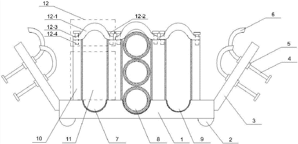
[0031] Such as figure 1 As shown, this embodiment provides a petroleum pipeline clamping transportation device that improves transportation efficiency, including a base 1, a moving roller 2 arranged at the lower end of the base 1, two side plates 3 symmetrically arranged on both sides of the base, vertically arranged on The screw rod 4 on the lower side of the side plate 3, the hoop 5 arranged on the upper and lower sides of the side plate 3 to fix the screw rod 4, and the arc-shaped clamping plate 6 arranged at the end of the screw rod 4 are characterized in that the base 1 is arranged in parallel and spaced apart Four blocking plates 10, the four blocking plates 10 divide the base 1 into three clamping areas 11, and the corresponding base areas in the three clamping areas 11 are respectively provided with semicircular grooves 7 and semicircular grooves. Groove two 8 and semicircular groove three 9, locking mechanisms 12 are provided at the tops of two adjacent blocking plate...

Embodiment 2

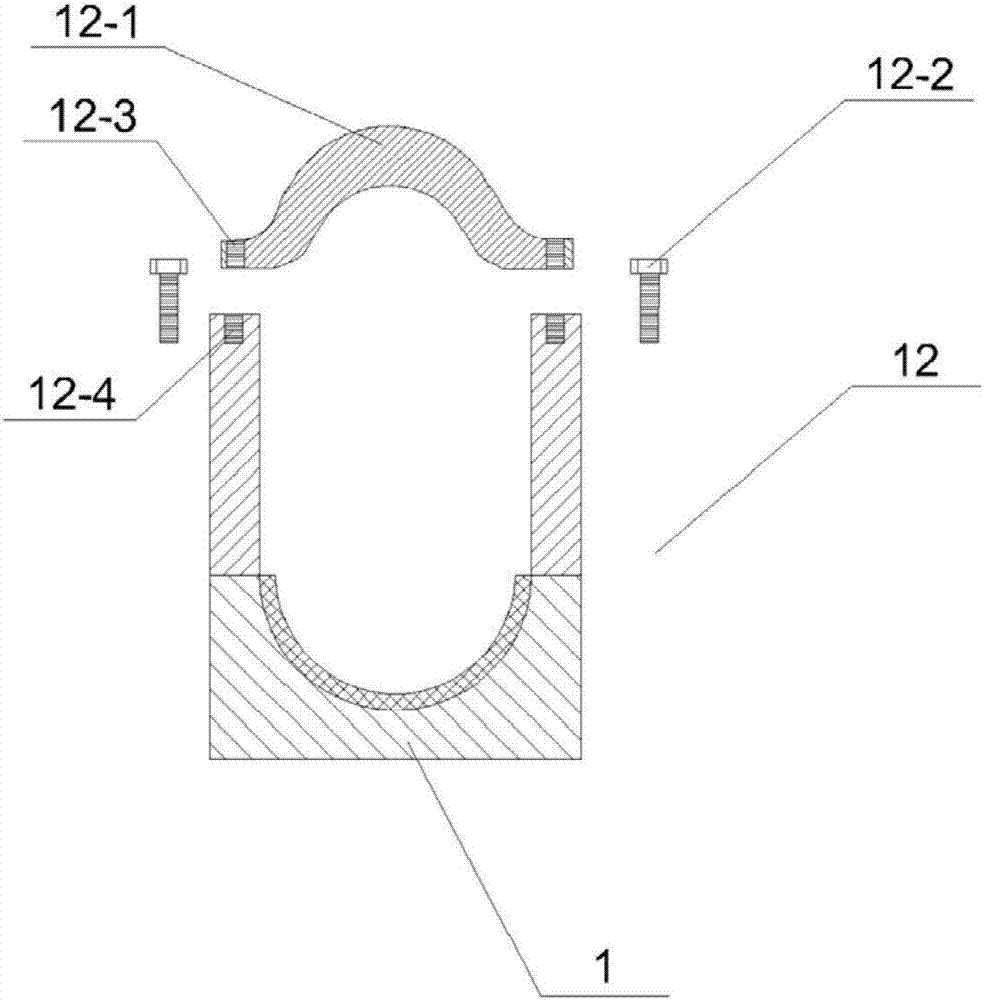
[0040] Such as Figure 1-2 As shown, this embodiment provides a petroleum pipeline clamping transportation device that improves transportation efficiency, including a base 1, a moving roller 2 arranged at the lower end of the base 1, two side plates 3 symmetrically arranged on both sides of the base, vertically arranged on The screw rod 4 on the lower side of the side plate 3, the hoop 5 arranged on the upper and lower sides of the side plate 3 to fix the screw rod 4, and the arc-shaped clamping plate 6 arranged at the end of the screw rod 4 are characterized in that the base 1 is arranged in parallel and spaced apart Four blocking plates 10, the four blocking plates 10 divide the base 1 into three clamping areas 11, and the corresponding base areas in the three clamping areas 11 are respectively provided with semicircular grooves 7 and semicircular grooves. Groove two 8 and semicircular groove three 9, locking mechanisms 12 are provided at the tops of two adjacent blocking pl...


PUM


Abstract

The invention discloses a petroleum pipeline clamping transportation device for improving transportation efficiency. The invention includes a base, a moving roller arranged at the lower end of the base, two side plates symmetrically arranged on both sides of the base, and a vertically arranged side plate on the lower side of the side plate. The screw, the hoop set on the upper and lower sides of the side plate to fix the screw and the arc-shaped clamping plate set on the end of the screw, four blocking plates are arranged in parallel and at intervals on the base, and the four blocking plates divide the base into three clips. The corresponding base areas in the three clamping areas are respectively provided with a semicircular groove, a semicircular groove 2 and a semicircular groove 3, and the adjacent two of the four blocking plates block The top of the plate is provided with a locking mechanism. The invention has a simple structure and makes full use of the space. By setting a plurality of semicircular grooves with different diameters on the base and cooperating with the locking mechanism, the transportation quantity of the oil pipeline is greatly increased, the transportation efficiency of the oil pipeline is improved, and the economic cost is saved. .

Description

technical field [0001] The invention relates to the technical field of petroleum machinery, and more particularly relates to a petroleum pipeline clamping transportation device for improving transportation efficiency. Background technique [0002] Oil pipeline is an essential tool in the process of oil extraction and transportation. Due to the heavy weight of the oil pipeline, manual trolleys are usually used for handling and moving the oil pipeline, which will consume a lot of manpower and material resources. At the same time, most of the oil pipelines are cylindrical, and sliding and collision friction cannot be avoided during the handling process. cause pipe wear. [0003] A utility model patent with the patent application number 201620537366.7 and the application date of June 6, 2016 discloses a clamping device for oil pipelines. There are at least 2 threaded through holes on the side plate, and a movable screw is set in the threaded through hole. The top of the screw ...

Claims


Application Information

Patent Timeline
Patent Type & Authority Applications(China)
IPC IPC(8): B62B3/10
CPCB62B3/104
Inventor 赵红昌雍海燕郭朦朦
Owner 弘毅天承知识产权股份有限公司
Why Eureka
Try Eureka