Fabric winding equipment

A kind of equipment and cloth technology, applied in the field of cloth winding equipment, can solve the problems of slow winding speed and inconvenient removal of cloth

Inactive Publication Date: 2017-10-20
刘芳
View PDF0 Cites 16 Cited by
  • Summary
  • Abstract
  • Description
  • Claims
  • Application Information

AI Technical Summary

Problems solved by technology

[0005] In order to overcome the disadvantages of slow cloth winding speed and inconvenient removal in the prior art, the technical

Method used


Image

  • Fabric winding equipment
  • Fabric winding equipment
  • Fabric winding equipment

Examples


Embodiment 1

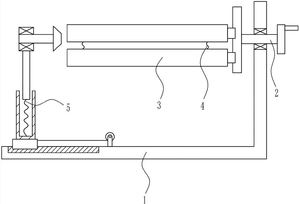
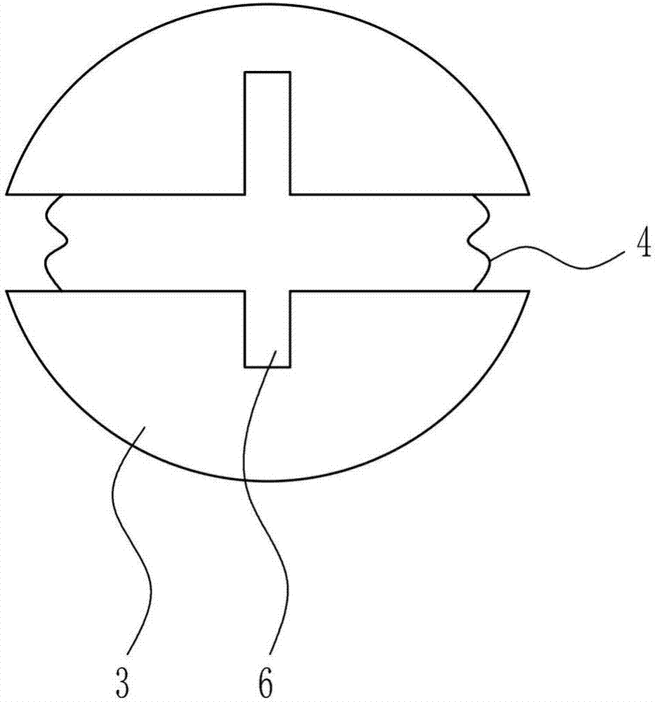
[0030] A cloth winding device such as Figure 1-6As shown, it includes a mounting frame 1, a rotating device 2, a semicircular cylinder 3, a first spring 4 and a stretching device 5. The upper part of the right wall of the mounting frame 1 is provided with a rotating device 2, and the left side of the rotating device 2 is arranged symmetrically up and down. There is a semi-circular drum 3, the first spring 4 is symmetrically connected between the upper part and the lower semi-circular drum 3, the bottom center of the upper semi-circular drum 3 and the top center of the lower semi-circular drum 3 are both provided with first grooves 6. The opening device 5 is provided on the left side of the inner bottom of the installation frame 1.

Embodiment 2

[0032] A cloth winding device such as Figure 1-6 As shown, it includes a mounting frame 1, a rotating device 2, a semicircular cylinder 3, a first spring 4 and a stretching device 5. The upper part of the right wall of the mounting frame 1 is provided with a rotating device 2, and the left side of the rotating device 2 is arranged symmetrically up and down. There is a semi-circular drum 3, the first spring 4 is symmetrically connected between the upper part and the lower semi-circular drum 3, the bottom center of the upper semi-circular drum 3 and the top center of the lower semi-circular drum 3 are both provided with first grooves 6. The opening device 5 is provided on the left side of the inner bottom of the installation frame 1.

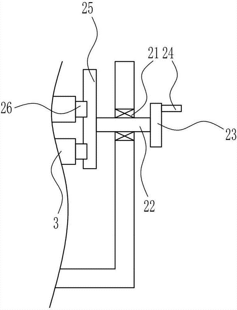
[0033] The rotating device 2 includes a first bearing seat 21, a first rotating shaft 22, a rotating disk 23, a handle 24, a first slide rail 25 and a first slider 26, and the upper part of the right wall of the mounting frame 1 is provided with ...

Embodiment 3

[0035] A cloth winding device such as Figure 1-6 As shown, it includes a mounting frame 1, a rotating device 2, a semicircular cylinder 3, a first spring 4 and a stretching device 5. The upper part of the right wall of the mounting frame 1 is provided with a rotating device 2, and the left side of the rotating device 2 is arranged symmetrically up and down. There is a semi-circular drum 3, the first spring 4 is symmetrically connected between the upper part and the lower semi-circular drum 3, the bottom center of the upper semi-circular drum 3 and the top center of the lower semi-circular drum 3 are both provided with first grooves 6. The opening device 5 is provided on the left side of the inner bottom of the installation frame 1.

[0036] The rotating device 2 includes a first bearing seat 21, a first rotating shaft 22, a rotating disk 23, a handle 24, a first slide rail 25 and a first slider 26, and the upper part of the right wall of the mounting frame 1 is provided with ...


PUM


Abstract

The invention relates to a winding device, in particular to a cloth winding device. The technical problem to be solved by the present invention is to provide a cloth winding device with fast cloth winding speed and convenient removal. In order to solve the above technical problems, the present invention provides such a cloth winding device, including an installation frame, etc.; a rotating device is arranged on the upper part of the inner right wall of the installation frame, and a semi-circular drum is symmetrically arranged on the left side of the rotating device, and the upper part is A first spring is symmetrically connected left and right between the lower semicircular drums, a first groove is formed in the bottom center of the upper semicircular drum and the top center of the lower semicircular drum, and a spreading device is provided on the left side of the inner bottom of the mounting frame. The invention drives the semicircular drum to rotate through the rotating device, so that the cloth can be wound up more quickly, and then the semicircular drum can be stretched and contracted by the stretching device, and the cloth can be wound well.

Description

technical field [0001] The invention relates to a winding device, in particular to a cloth winding device. Background technique [0002] Cloth is a commonly used material in decorative materials. Including chemical fiber carpets, non-woven wall coverings, linen cloth, nylon cloth, colored tape, flannel and other fabrics. Cloth plays a considerable role in the decorative display, and is often the main force that cannot be ignored in the entire sales space. Extensive use of fabrics for wall decoration, partitions, and background treatment can also form a good commercial space display style. In the process of storing or transporting the cloth, it is often necessary to wrap the cloth to save space for storage or transportation. However, if the cloth cannot be wound up quickly and the wound cloth can be easily removed during the winding process, the work efficiency will be affected. [0003] To sum up, there is a need to develop a fabric winding device with fast winding speed...

Claims


Application Information

Patent Timeline
IPC IPC(8): B65H75/24B65H18/02B65H18/10B65H19/30
CPCB65H75/242B65H18/028B65H18/10B65H19/30B65H2301/418B65H2701/1133B65H2701/174
Inventor 刘芳
Owner 刘芳
Why Eureka
Try Eureka