
Support systems, modularized tents, modularized tent set and draining method of modularized tent set

A bracket system and modular technology, applied in the field of tents, can solve the problems of not being able to realize close side by side, not having a drainage system, and not being able to realize modular splicing, etc., so as to achieve the effect of improving the use performance

Active Publication Date: 2017-10-20
ZHUHAI LIRI TENT TECH
View PDF6 Cites 7 Cited by
  • Summary
  • Abstract
  • Description
  • Claims
  • Application Information

AI Technical Summary

Problems solved by technology

[0003] The problem with the existing tents is that when the existing tents are modularized and extended, the single tent can only be set as a rectangle, and then a plurality of tents are simply pieced together to form a tent group.
After all, the tent group is composed of multiple tents, and each tent needs to be drained. Therefore, the patchwork of tents cannot be closely arranged side by side, and water tanks need to be installed between adjacent tents. The roof flow water of the tents on both sides of the sink is dredged and drained
Therefore, the existing tents cannot achieve compact modular splicing and do not have a good drainage system

Method used


Image

  • Support systems, modularized tents, modularized tent set and draining method of modularized tent set
  • Support systems, modularized tents, modularized tent set and draining method of modularized tent set
  • Support systems, modularized tents, modularized tent set and draining method of modularized tent set

Examples


no. 1 example

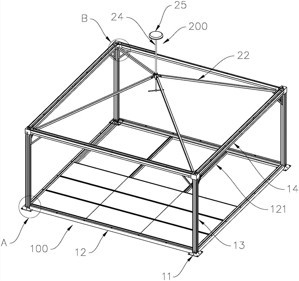
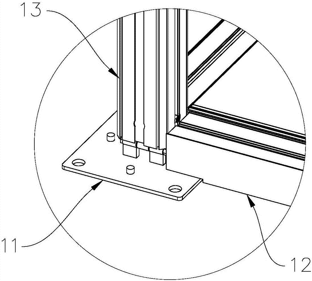
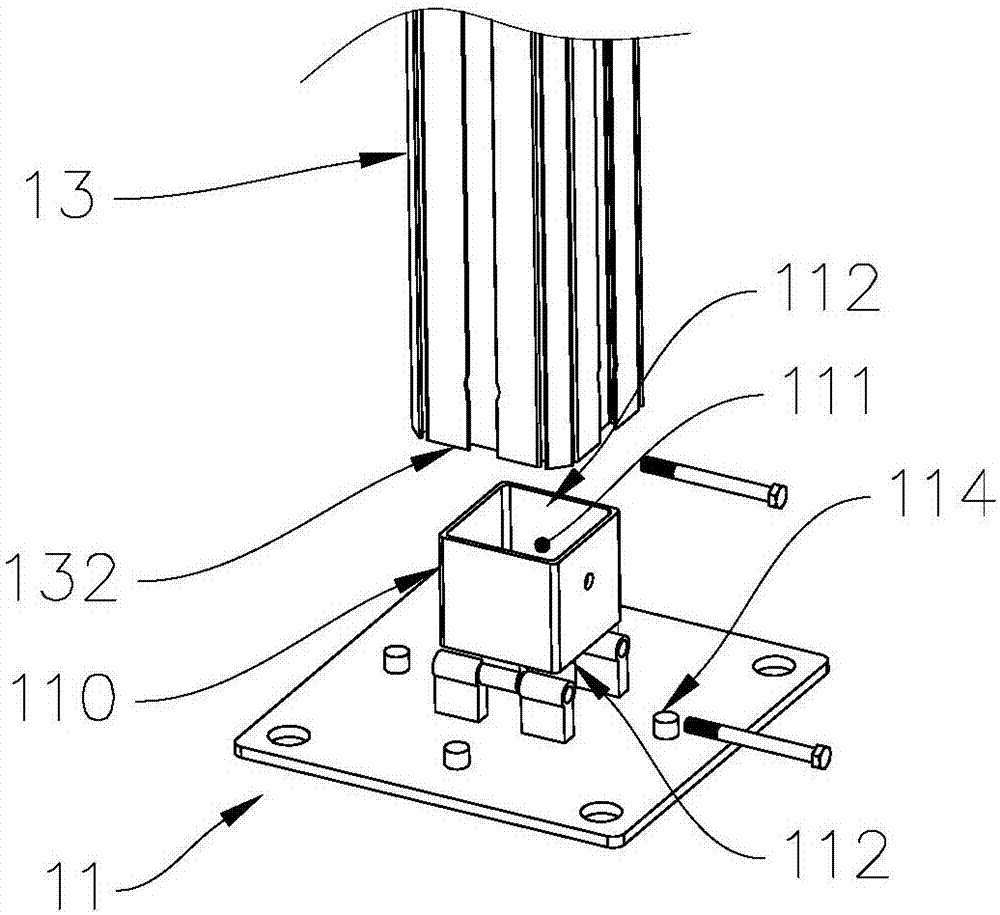
[0044] see figure 1 , figure 1It is a structural diagram of the support system 100 in the first embodiment of the modular tent of the present invention. The modular tent includes a bracket system 100 , a wall unit (not shown in the figure), a floor unit and a tarpaulin (not shown in the figure) arranged on the upper end of the bracket system 100 . The bracket system 100 includes a base 11, a bottom beam 12, a column 13, a beam 14 and a top bracket assembly 200, the base 11 is fixed on the ground, the bottom beam 12 is connected between the two bases 11, the column 13 is installed on the base 11, and the beam 14 is connected between the upper ends of two columns 13 , and the beam 14 is parallel to the bottom beam 12 . The wall unit is arranged between the beam and the bottom beam, the floor unit is supported on the bottom beam 12 and the secondary bottom beam 121 , the edge of the tarpaulin is fixedly connected to the beam 14 , and the tarpaulin is supported by the top bracke...

no. 3 example

[0057] see Figure 13 , Figure 14 and Figure 15 , Figure 13 It is a structural diagram of the bracket system in the third embodiment of the modular tent of the present invention, Figure 14 for Figure 13 The magnified view at E in the middle, Figure 15 It is the working principle diagram of the third embodiment of the modular tent of the present invention. Since the bracket system 5 in this embodiment is completely the same as that in the first embodiment, it will not be described in detail. The top bracket assembly 6 includes a connecting plate 61 and a steel cable 62 . The connecting plate 61 is connected between two adjacent beams 54, and the connecting plate 61 is close to the column 53; the modular tent includes four columns 53 arranged in a rectangular array, and each column 53 is provided with a back against it A connecting plate 61 , a steel cable 62 is connected between the two connecting plates 61 corresponding to the two columns 53 arranged diagonally, a...


PUM


Abstract

The invention provides support systems, modularized tents, a modularized tent set and a draining method of the modularized tent set. The modularized tents each comprise the corresponding support system and a canopy. The support systems each comprise vertical columns, a base and cross beams. The cross beams are connected to the upper ends of the vertical columns. The multiple modularized tents form the modularized tent set. The modularized tents share the cross beams and the vertical columns. Water flows into the cross beams from the canopies. The water in the cross beams flows into the vertical columns, and the water in the vertical columns flows to the ground. Concealed draining lines are formed in the support systems, the modularized tents are connected more closely, and the using performance of the modularized tents is improved through a concealed and effective draining system.

Description

technical field [0001] The invention relates to the field of tents, in particular to a support system for a tent, a modular tent formed by the support system, a modular tent group composed of a plurality of modular tents, and a drainage method for the modular tent group. Background technique [0002] An existing quick-install tent includes a bracket, a wall unit, and a tarpaulin fixed on the upper part of the tent bracket; the bracket shown includes a middle column and a beam, and the middle column is located between two wall units; the beam limit The two adjacent wall units connected to the top of the middle column are fixed by a lock relative to the middle column between them; the bracket also includes a column, a ground beam and a base; the base is rigidly connected to the bottom of the column and the base is fixedly connected to the ground; the ground beam is set Between the two bases, the crossbeam is arranged between the two uprights, and the two uprights support and l...

Claims


Application Information

Patent Timeline
Patent Type & Authority Applications(China)
IPC IPC(8): E04H15/00E04H15/32E04H15/34
CPCE04H15/00E04H15/32E04H15/34
Inventor 梁维民
Owner ZHUHAI LIRI TENT TECH
Learn More