Handle lock

A technology of horn lock and deadbolt, which is used in building locks, lock shells, door/window accessories, etc., can solve the problems of difficult assembly, many parts, easy failure of return springs, etc., and achieves simple structure, few parts, The effect of convenient assembly and debugging

Inactive Publication Date: 2017-10-20
CMECH (GUANGZHOU) INDUSTRIAL LTD
View PDF7 Cites 0 Cited by
  • Summary
  • Abstract
  • Description
  • Claims
  • Application Information

AI Technical Summary

Problems solved by technology

This kind of structure is relatively complicated, and there are many parts, so it is difficult to assemble; and after a long time of use, the return spring is prone to failure, and it is difficult to insert the deadbolt into the corresponding hole on the door frame.

Method used


Image

  • Handle lock
  • Handle lock
  • Handle lock

Examples


Embodiment Construction

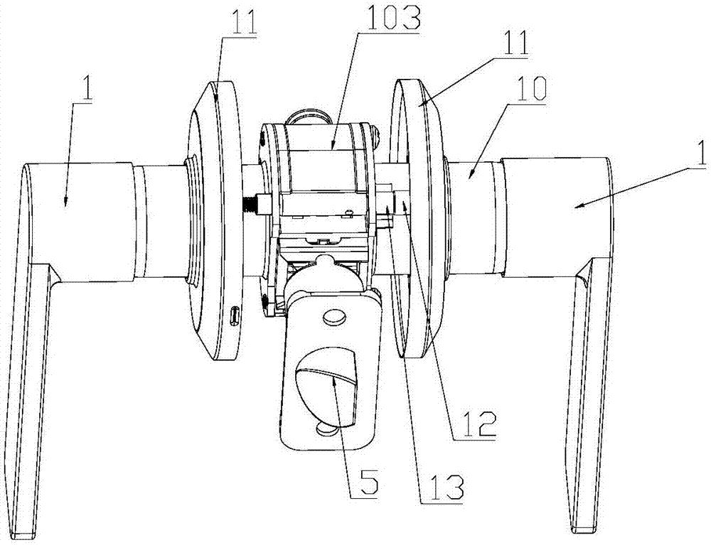
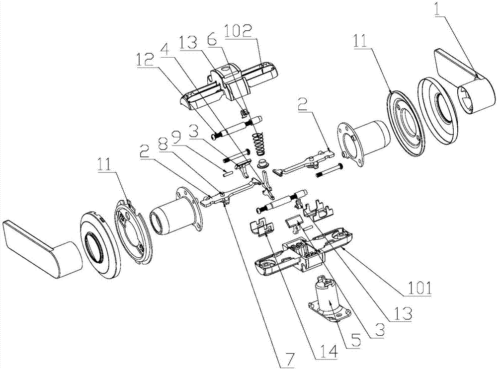
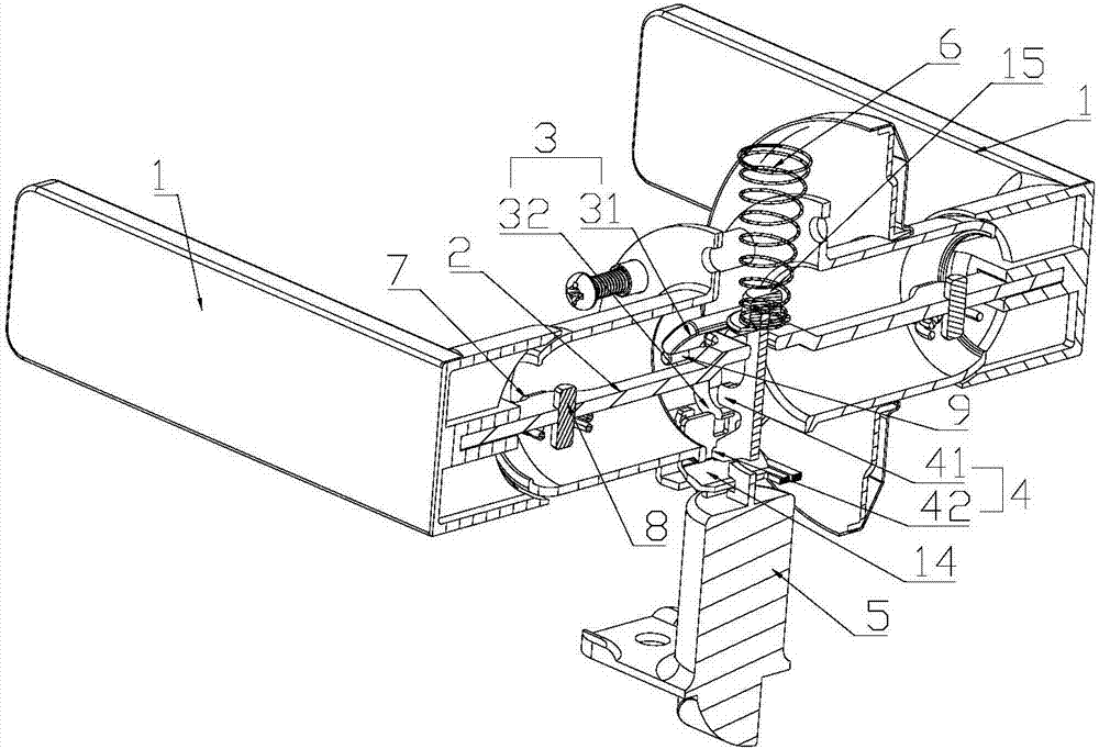
[0031] Such as Figure 1-Figure 9 As shown, the present invention provides a horn lock, comprising a handle 1, a driving lever 2, a reversing block 3, a slider 4, a dead bolt 5 and a reset device for resetting the dead bolt 5, a driving lever 2, a reversing block 3 And the slider 4 is located in the housing 10, the lever 2 and the reversing block 3 are hinged with the housing 10, the reversing block 3 includes a rotating part 31 and a touch part 32, and the rotating part 31 and the actuating part 32 are respectively located on the reversing block 3 on both sides of the hinge shaft, one end of the driving lever 2 is connected to the handle 1, and the other end is adjacent to the rotating part 31, one end of the slider 4 is connected to the deadbolt 5, and the other end is adjacent to the touching part 32, and the driving lever 2 The rotation triggers the rotating part 31 to rotate, thereby driving the rotating part 32 to push up the slider 4 . Turn the rotating part 31 of the ...


PUM


Abstract

The invention provides a handle lock which comprises handles, stirring rods, reverse rotating blocks, a sliding block, a lock tongue and a reset device enabling the lock tongue to reset. The stirring rods, the reverse rotating blocks and the sliding block are located in a shell. The stirring rods and the reverse rotating blocks are hinged to the shell. Each reverse rotating block comprises a rotating portion and a touch portion. Each rotating portion and the corresponding touch portion are located on the two sides of a hinged shaft of the corresponding reverse rotating block correspondingly. One end of each stirring rod is connected with the corresponding handle, and the other end of each stirring rod and the corresponding rotating portion are arranged adjacently. One end of the sliding block is connected with the lock tongue, and the other end of the sliding block and the touch portions are arranged adjacently. The stirring rods rotate to touch the rotating portions of the reverse rotating blocks to rotate, and therefore the touch portions of the reverse rotating blocks touch the sliding block, and the sliding block is jacked up. The handle lock is simple in structure and is provided with few parts.

Description

technical field [0001] The invention provides a horn lock. Background technique [0002] In the prior art, there are many types of locks. The horn lock is a relatively common one with a wide range of applications. The structure of the horn lock is also relatively diverse. The existing more common horn lock includes a deadbolt and a sliding frame connected with the deadbolt. And the cam arranged in the sliding frame, the rotation of the cam drives the sliding frame to rotate, thereby driving the dead bolt connected with the sliding frame to retract, and a reset spring is set to reset the sliding frame. This structure is more complicated, and there are many parts, and it is difficult to assemble; and after a long time of use, the return spring is prone to failure, and it is difficult to insert the dead bolt into the corresponding hole on the door frame. Contents of the invention [0003] Based on the above deficiencies, the technical problem to be solved by the present inve...

Claims


Application Information

Patent Timeline
Patent Type & Authority Applications(China)
IPC IPC(8): E05B15/00E05B3/00
CPCE05B3/00E05B15/00E05B9/08E05B63/006E05C1/14E05B9/02E05B15/0033E05B15/02E05B63/0056
Inventor 不公告发明人
Owner CMECH (GUANGZHOU) INDUSTRIAL LTD
Why Eureka
Try Eureka