
A water pump

A water pump and water cut-off technology, which is applied in the direction of pumps, pump components, variable-capacity pump components, etc., can solve the problems of poor water sealing and large vibration at the water sealing port, and achieve the effects of low cost, slow movement, and ensuring tightness

Active Publication Date: 2020-02-18
宁波川渡流体科技有限公司
View PDF5 Cites 0 Cited by
  • Summary
  • Abstract
  • Description
  • Claims
  • Application Information

AI Technical Summary

Problems solved by technology

[0003] The purpose of the present invention is to solve the problem that the existing water cut-off pump is prone to large vibration and the water seal at the water sealing port is not tight when the water inlet pressure is high. It can ensure tight sealing of water and avoid or reduce vibration

Method used


Image

  • A water pump
  • A water pump
  • A water pump

Examples


Embodiment 1

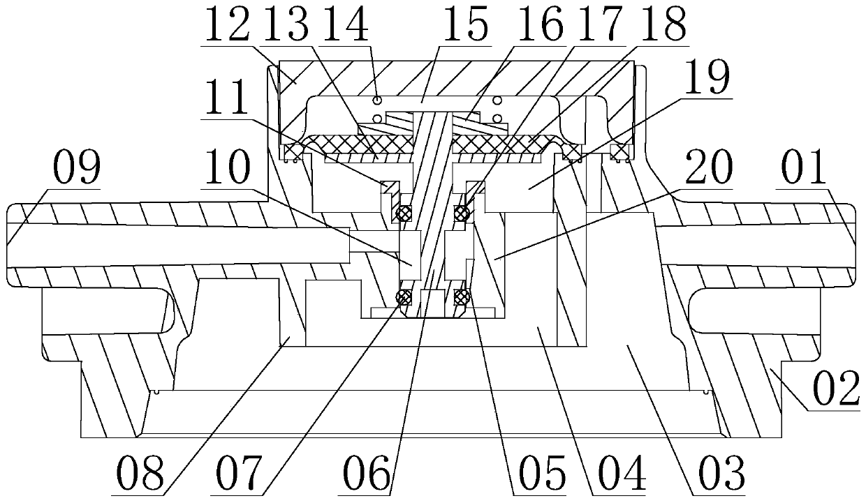
[0025] Such as figure 1 As shown, a water cut-off pump includes a pump body and a water cut-off assembly arranged in the pump body, wherein the pump body includes a pump head body 02 and an upper cover 12, and the pump head body 02 is composed of a water inlet 01, a sealing ring sleeve 08, an outlet Water port 09, water sealing sleeve 1 20, and raw water chamber 1 03 and water outlet chamber 1 04 which are sequentially arranged on the connection channel from water inlet 01 to water outlet 09, raw water chamber 1 03 and water outlet chamber 1 04 are covered by a sealing ring 08 separate composition. In this embodiment, the upper cover 12 is sealingly connected with the top of the pump head body 02 and forms a housing cavity with the pump head body 02. The water cut-off component separates the housing cavity to form two upper and lower cavities, and the lower cavity is The water outlet chamber three 19 connected with the water outlet chamber one 04, and the cavity above is the ...

Embodiment 2

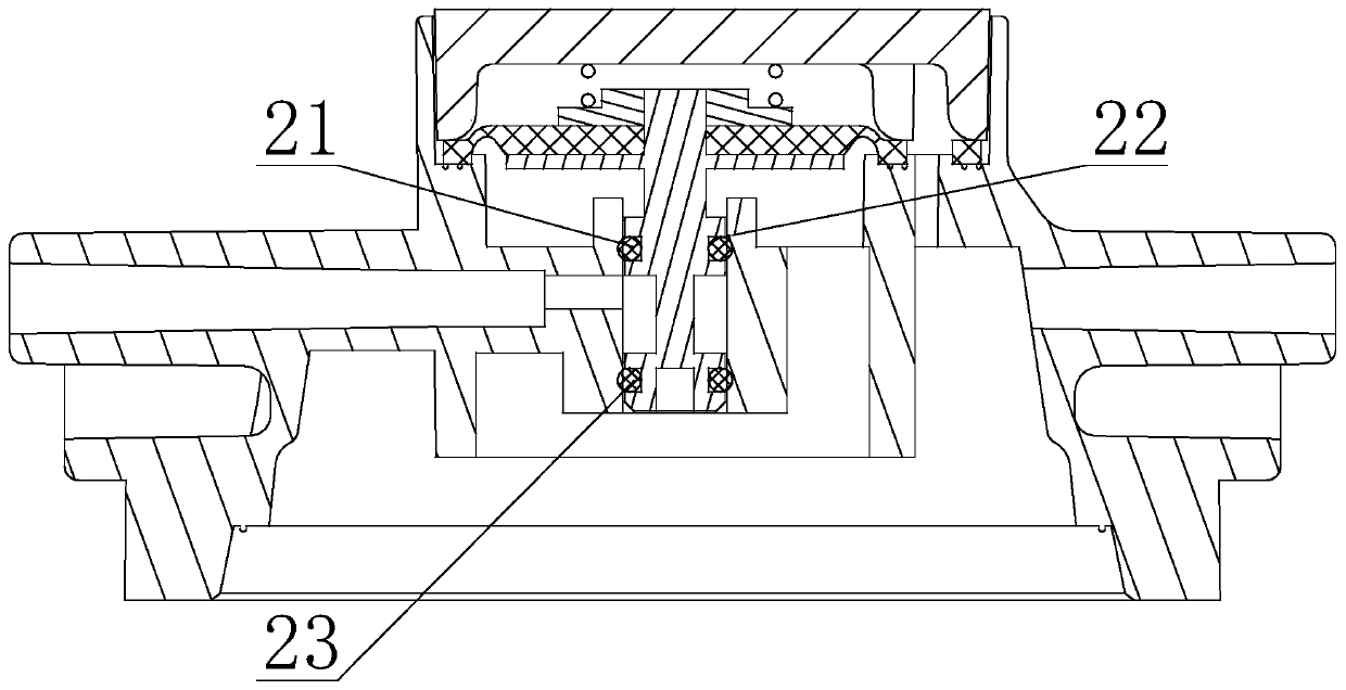
[0031] Such as figure 2 As shown, the difference between this embodiment and Embodiment 1 is that the water sealing port of this embodiment is the water sealing port 2 22 formed by the opening of the upper end of the water sealing sleeve 1 20, and the two sleeves set on the control rod 1 06 of this embodiment The sealing rings are respectively the water sealing ring 2 21 located on the upper side of the water inlet chamber 10 and the sealing ring 2 23 located on the lower side of the water inlet chamber 10 .

[0032] When this embodiment is applied, the water sealing ring 2 21 is embedded in the water outlet cavity 3 19 when the sealing water port 22 is opened, and the water sealing ring 2 21 is sealed with the inner wall of the upper opening of the water sealing sleeve 1 20 when the sealing water port 2 22 is closed. touch.

Embodiment 3

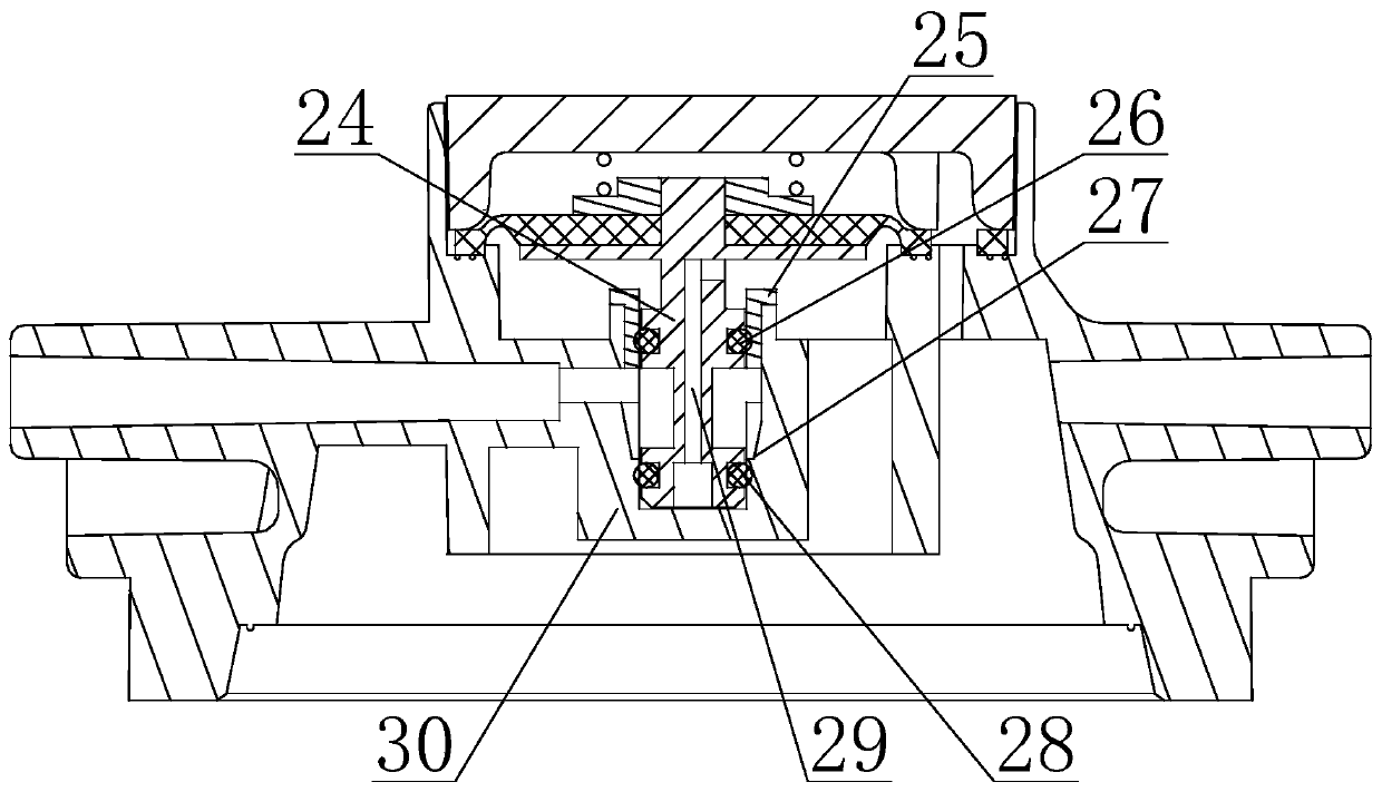
[0034] Such as image 3 As shown, the difference between this embodiment and Embodiment 1 is that the water sealing sleeve of this embodiment is the water sealing sleeve 2 30 with the lower end sealed, the control rod is the control rod 2 24 forming a water passage 29, and the water sealing The part of sleeve two 30 located above the water inlet chamber two 10 is replaced by the auxiliary sealing ring sleeve one 11 by the auxiliary sealing ring sleeve two 25, and the water sealing port is set on the water sealing sleeve two 30 and located at the water outlet chamber two The water sealing port 3 27 at the bottom of 10, and the two sealing rings set on the control rod 2 24 are the sealing ring 3 26 on the upper side of the water inlet chamber 10 and the water sealing ring located on the lower side of the water inlet chamber 2 10 Three 28.

[0035] In this embodiment, the lower end of the control rod two 24 is embedded in the water sealing sleeve two 30 and a damping chamber is ...


PUM


Abstract

The invention discloses a water disconnecting pump. The water disconnecting pump comprises a water inlet, a water outlet, a first raw water cavity, a first water outlet cavity, a water sealing opening, a water disconnecting assembly, a water sealing sleeve and a third water outlet cavity, wherein the third water outlet cavity is connected with the first water outlet cavity. The upper opening end of the water sealing sleeve is arranged in the third water outlet cavity, and the lower end of the water sealing sleeve is arranged in the first water outlet cavity. The water disconnecting assembly comprises a control rod and two sealing rings arranged on the control rod in a sleeving mode. The control rod penetrates through the third water outlet cavity, and the lower end of the control rod is embedded in the water sealing sleeve. The control rod, the two sealing rings on the control rod and the water sealing sleeve form a second water outlet cavity. The water sealing opening is formed in the water sealing sleeve. The two sealing rings on the control rod are located on the upper side and the lower side of the second water outlet cavity correspondingly. The sealing ring which is located on the opposite side of the second water outlet cavity with the water sealing opening makes close contact with the inner wall of the water sealing sleeve. The sealing ring which is located on the same side of the second water outlet cavity with the water sealing opening conducts opening-closing control on the water sealing opening under driving of the situation that the water disconnecting assembly drives the control rod to shift up and down. According to the water disconnecting pump, tight water sealing can be ensured when the water inlet pressure is large, and vibration can be eliminated or reduced.

Description

technical field [0001] The invention relates to a water flow interruption control assembly, in particular to a water interruption pump. Background technique [0002] The household pure water machine system is usually equipped with a water cut-off device to control the on-off of the waterway. As one of the many devices that can realize the water cut-off function, the water cut-off pump is widely used in the household pure water machine system. Existing water cut-off pumps are usually provided with a raw water chamber, a water outlet chamber and a water inlet connected to the raw water chamber, and a water outlet connected to the water outlet chamber, and a water cut-off assembly for controlling the opening and closing of the water sealing port is provided on the channel connecting the inlet and outlet. When the water pressure of the existing cut-off water pump is high, problems such as large vibration and poor water sealing at the water sealing port are prone to occur, which ...

Claims


Application Information

Patent Timeline
Patent Type & Authority Patents(China)
IPC IPC(8): F04B43/02F04B53/10
CPCF04B43/02F04B53/10
Inventor 吴瑞昌
Owner 宁波川渡流体科技有限公司
Learn More