Multifunctional eddy ceiling fan

A multi-functional, eddy current technology, applied in fluid heaters, components of pumping devices for elastic fluids, air heaters, etc., can solve the problems of increasing user decoration costs, insufficient comfort, and small air supply range, etc. Achieve the effects of good air circulation, save installation space, and save decoration costs

Pending Publication Date: 2017-10-20
黄祖潜
View PDF5 Cites 4 Cited by
  • Summary
  • Abstract
  • Description
  • Claims
  • Application Information

AI Technical Summary

Problems solved by technology

[0003] At present, there are two kinds of ceiling fans on the market: traditional ceiling fans and centrifugal ceiling fans. The air direction of traditional ceiling fans is directly from top to bottom, and the air supply range is small and uneven. The wind blows directly to the human body, which is not comfortable enough. Although the centrifugal ceiling fan solves the safety problem, the way of blowing air is still in a "columnar shape" after direct pressurization, and the wind directly blows to the human body, causing discomfort; Each wind cannot form a uniform fusion; the air supply distance and coverage are affected by the power of the motor. If you need to achieve a better air supply distance, you need to use a high-power motor, which will lead to higher energy consumption and the generated after the machine is running. hot and windy
[0004] In addition, most of the ceiling fans installed in many homes and offices now only have the function of blowing air, which has a single function and cannot meet the requirements of different users. For example, when the user needs lighting or heating functions, additional lamps and heaters need to be installed. , which will undoubtedly occupy more space and increase the user's decoration cost

Method used


Image

  • Multifunctional eddy ceiling fan
  • Multifunctional eddy ceiling fan
  • Multifunctional eddy ceiling fan

Examples


Embodiment Construction

[0032] The present invention will be described in further detail below in conjunction with the accompanying drawings and specific embodiments.

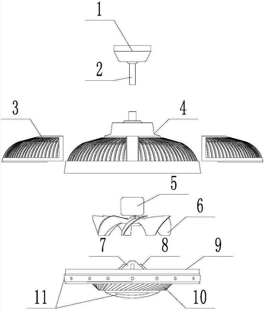
[0033] Such as Figure 1~3 As shown, a multifunctional vortex ceiling fan, including

[0034] The support assembly includes an installation top base 1 and a support rod 2, the installation top base 1 is installed on the ceiling, and the upper end of the support rod 2 is connected to the installation top base 1;

[0035] The housing includes an air inlet cover 4 provided with an air inlet and an air outlet cover 9 provided with an air outlet. The air inlet cover 4 and the air outlet cover 9 are detachably connected to form a cavity housing. The air inlet cover 4 is installed on the lower end of the support rod 2, and the conical air guide tube 7 is arranged in the described air outlet cover 9, and the air outlet of the described air outlet cover 9 is a spiral air outlet window 10 at an oblique angle;

[0036] The fan assembly include...


PUM


Abstract

The invention relates to a multifunctional eddy ceiling fan. The ceiling fan comprises a supporting assembly, a shell, a fan assembly, a heating element and a lamp assembly, wherein the supporting assembly comprises a mounting top seat and a supporting rod, and the mounting top seat is installed on the ceiling and connected with the upper end of the supporting rod; the shell comprises an air inlet hood and an air outlet hood, the air inlet hood is installed at the lower end of the supporting rod, and a conical air duct is arranged in the air outlet hood; the air duct is provided with the heating element, and the air outlet of the air outlet hood is a helical air outlet window with an inclined angle; the fan assembly comprises a motor and a spiral fan blade, and the spiral fan blade is connected with the power output shaft of the motor and driven by the motor to rotate; the lamp assembly comprises an illuminating lamp and a transparent lampshade which are installed at the bottom and the side of the air outlet hood receptively. The multifunctional eddy ceiling fan has the advantages of a wide air supply range and uniform air supply, and can make a human body feel comfortable; the ceiling fan not only can provide cold and warm air, but also has a lighting function, and meanwhile, the installation space and the decoration cost are saved.

Description

technical field [0001] The invention relates to the field of household appliances, in particular to a multifunctional eddy current ceiling fan. Background technique [0002] The ceiling fan is a blower tool fixedly installed on the ceiling. In the hot summer, the cool air blown by the ceiling fan can play a good role in cooling down. [0003] At present, there are two kinds of ceiling fans on the market: traditional ceiling fans and centrifugal ceiling fans. The air direction of traditional ceiling fans is directly from top to bottom, and the air supply range is small and uneven. The wind blows directly to the human body, which is not comfortable enough. Although the centrifugal ceiling fan solves the safety problem, the way of blowing air is still in a "columnar shape" after direct pressurization, and the wind directly blows to the human body, causing discomfort; Each wind cannot form a uniform fusion; the air supply distance and coverage are affected by the power of the m...

Claims


Application Information

Patent Timeline
Patent Type & Authority Applications(China)
IPC IPC(8): F04D25/08F04D29/00F21V33/00F24H3/04
CPCF04D25/088F04D29/002F21V33/0096F24H3/04
Inventor 段小青
Owner 黄祖潜
Why Eureka
Try Eureka