
Automatic tracking emitter

An automatic tracking and projectile technology, applied in the direction of projectiles, offensive equipment, weapon types, etc., can solve the problems of projectiles not being able to track targets and low strike accuracy, and achieve optimal spatial layout, improve strike accuracy, and improve tracking capabilities Effect

Active Publication Date: 2017-10-20
来安县永阳知识产权运营有限公司
View PDF6 Cites 0 Cited by
  • Summary
  • Abstract
  • Description
  • Claims
  • Application Information

AI Technical Summary

Problems solved by technology

[0005] Therefore, the technical problem to be solved by the present invention is to overcome the technical defects that the launcher in the prior art cannot track the target and the strike accuracy is low

Method used


Image

  • Automatic tracking emitter
  • Automatic tracking emitter
  • Automatic tracking emitter

Examples


Embodiment 1

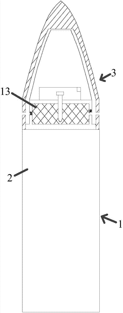
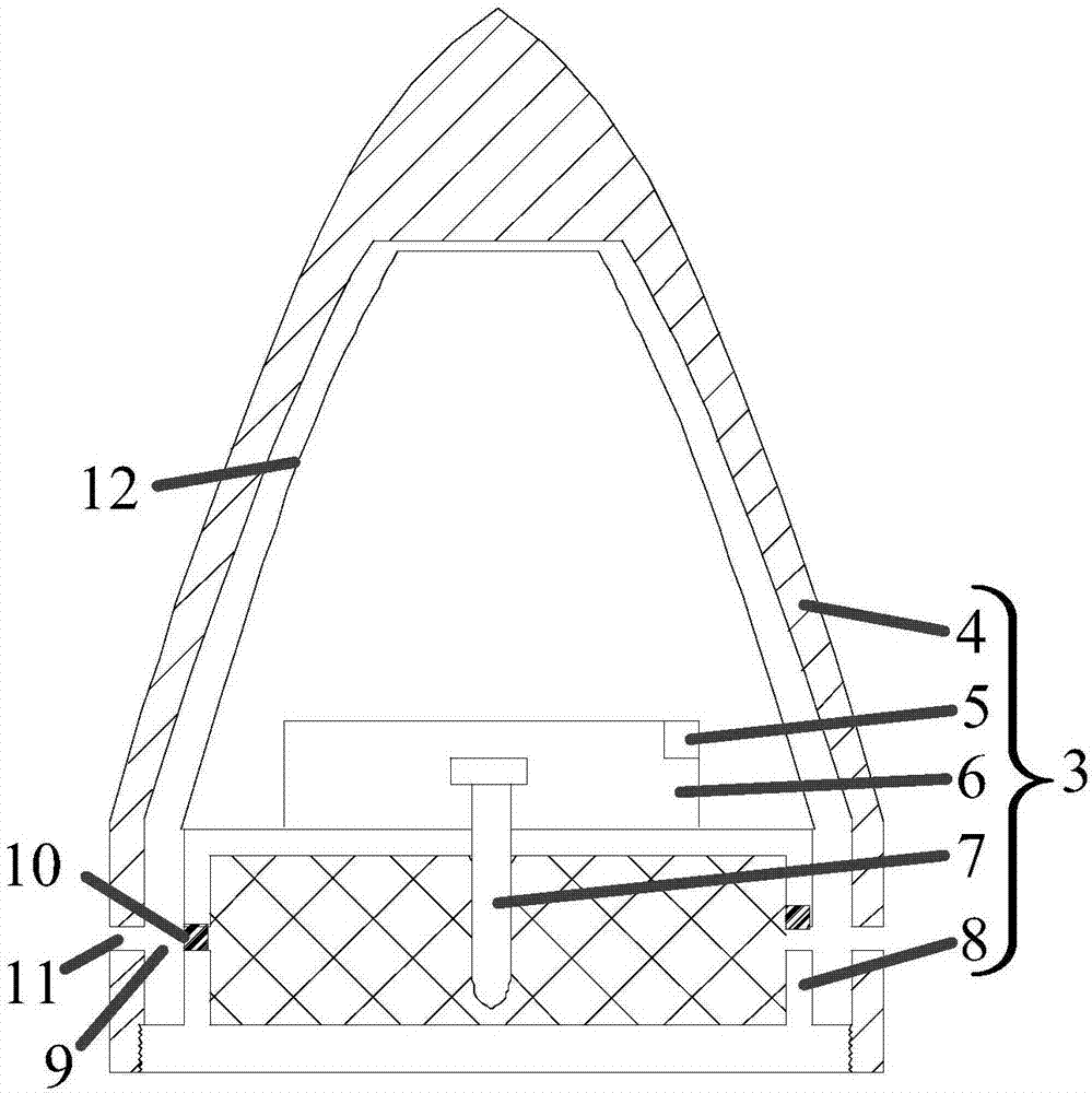
[0042] Such as figure 1 with figure 2 The auto-tracking projectile shown is a bullet, which consists of:

[0043] The signal transmitter is pre-set on the tracked target and is used to transmit position signals;

[0044] The projectile body 1 is provided with a primary motive medium 2 in the inner cavity of the projectile body 1;

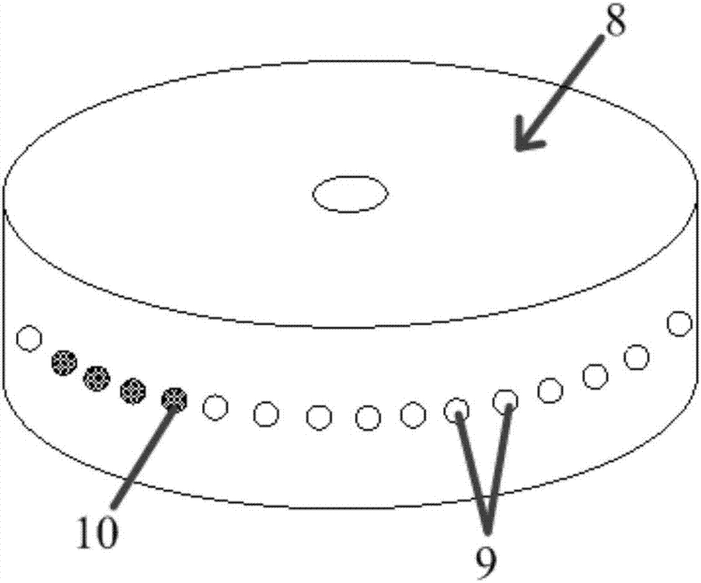
[0045]The launch head 3 is arranged on the front end of the projectile body 1, and it includes a signal receiver 5, a controller 6, an excitation structure 7 arranged in the cavity of the bullet shell 4 made of metal material, and a secondary power is accommodated. The disk-shaped power chamber 8 made of the thermal insulation material of the medium 13, the excitation structure is used to receive the excitation control command and excite the secondary power medium 5 in the power chamber 6, and the secondary power medium 5 is propellant; image 3 As shown, the disk-shaped power chamber 8 is provided with at least one injection channel 9 extendin...

Embodiment 2

[0052] Automatically track projectiles as bullets, which include:

[0053] The signal transmitter is pre-set on the tracked target and is used to transmit position signals;

[0054] The projectile body 1 is provided with a primary motive medium 2 in the inner cavity of the projectile body 1;

[0055] The launch head 3 is arranged on the front end of the projectile body 1, and it includes a signal receiver 5, a controller 6, an excitation structure 7 arranged in the cavity of the bullet shell 4 made of metal material, and a secondary power is accommodated. The disk-shaped power chamber 8 made of the thermal insulation material of the medium 13, the excitation structure is used to receive the excitation control command and excite the secondary power medium 5 in the power chamber 6, and the secondary power medium 5 is propellant; image 3 As shown, the disk-shaped power chamber 8 is provided with at least one injection channel 9 extending to the outside of the side of the launch...


PUM


Abstract

The invention provides an automatic tracking emitter. The automatic tracking emitter comprises a signal emitter, an emitter body and an emitting head, wherein the emitting head comprises a signal receiver, a controller and a motivating structure which are arranged in an inner cavity of a housing of a bullet as well as a powerhouse where a secondary dynamic medium is accommodated; the motivating structure is used for receiving a motivation control command and motivating the secondary dynamic medium in the powerhouse; at least one jet channel which extends to the outer side of the side face of the emitting head is arranged on the powerhouse; a control valve is arranged in each of the jet channels, the signal receiver receives a position signal of the signal emitter and sends the position signal to the controllers, and the controllers control the motivating structure to ignite the secondary dynamic medium and control the control valves to be turned on and off so as to change the flight direction of the emitting head. The automatic tracking emitter provided by the invention solves the problem that the emitter in the prior art cannot track a target and is low in striking precision.

Description

technical field [0001] The invention belongs to the technical field of launching devices, is suitable for non-rotating and advancing projectiles, and in particular relates to an automatic tracking projectile. Background technique [0002] Projectiles in the prior art mainly include a projectile body and a projectile head. When the trigger is pulled, the projectile head is excited to separate from the projectile body and shoot out from the gun bore to hit the target. If the position of the target changes, after the projectile is fired from the barrel, since the launch head can only move in one direction, it is impossible to strike the target precisely, which reduces the accuracy of the strike. [0003] In order to solve the above technical problems, Chinese patent document CN 105498254 A discloses a emitter, such as Figure 5 As shown, it comprises: emitter body body 101; emitter body 102, has the channel 103 of rear end opening; There is an installation cavity, and the laun...

Claims


Application Information

Patent Timeline
IPC IPC(8): F42B10/66F42B10/02
CPCF42B10/02F42B10/663
Inventor 王海龙
Owner 来安县永阳知识产权运营有限公司
Learn More