
Optical device

a technology of optical devices and optical components, applied in the direction of pyrometry using electric radation detectors, direction controllers, instruments, etc., can solve the problems of difficult integration, inability to accurately evaluate the state of motion, and the distance and three-dimensional structure of the target object, so as to improve the evaluation effect, and the working range is long

Active Publication Date: 2015-11-24
MBDA DEUTSCHLAND GMBH
View PDF18 Cites 0 Cited by
  • Summary
  • Abstract
  • Description
  • Claims
  • Application Information

AI Technical Summary

Benefits of technology

The patent suggests using high resolution measurements of dynamic targets to improve hit accuracy and facilitate target classification and discrimination. By measuring the distance of a target from the seeker head and their relative motion in all three degrees of freedom, the sensor can better determine the direction of the target early on. This allows for better target engagement and improved accuracy of the missile's aim. Additionally, by measuring the depth dimension of the target object along with the measurement of the nominal angular velocity, the sensor can better discriminate real targets from false targets.

Problems solved by technology

The signatures enable the seeker head to recognize target objects and permit a coarse target localization in the two dimensional angular space, but the signatures deliver only very inaccurate data about the state of motion, the distance and the three dimensional structure of these target objects.
However, the size and the architecture of the radar sensors make it difficult to integrate them into a seeker head, so that for this reason the radar sensors are often provided, for example, as external sensors independent of the seeker head.

Method used


Image

  • Optical device
  • Optical device
  • Optical device

Examples


Embodiment Construction

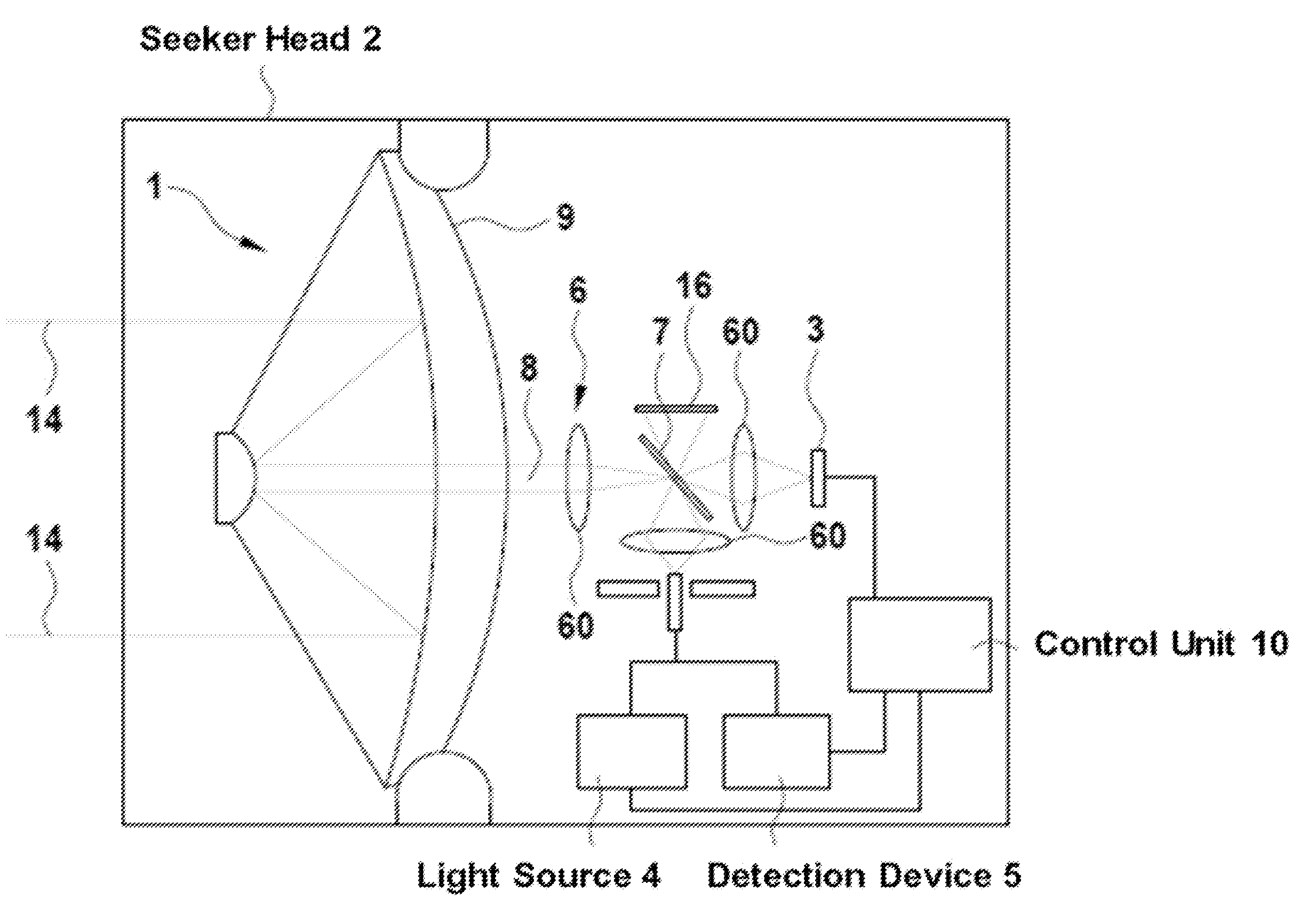
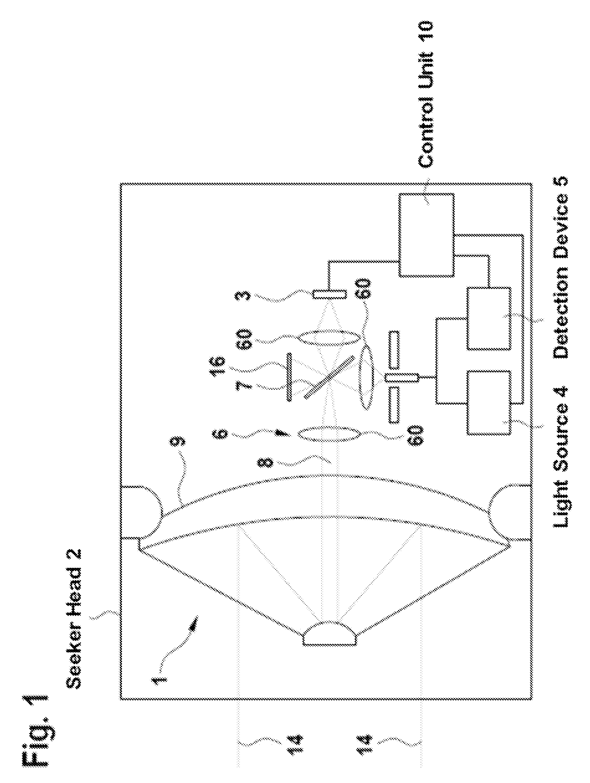
[0018]FIG. 1 shows an optical device 1, which can be, in particular, a part of a seeker head 2 of a missile. The optical device 1 comprises a reflector telescope 9, which bundles the optical radiations 14 from the surrounding area of the optical device 1 and passes these optical radiations as a common beam path 8 to an optical system 6. The optical system 6 comprises a plurality of lenses 60 and a dichroic beam splitter 7 and is configured to divide the common beam path 8, in order to guide this common beam path to an optical sensor 3 and to a detection device 5. The optical sensor 3 is, in particular, an infrared sensor with a plurality of pixels; and this infrared sensor can recognize a target by means of its optical signature. This signature represents, in particular, the distribution of the reflected or emitted radiation intensity on the surface of the target.

[0019]Furthermore, the dichroic beam splitter 7 of the optical system 6 makes it possible for a light source 4 to introdu...


PUM


Abstract

An optical device for a missile seeker head includes an optical sensor with a plurality of pixels, a light source, a detection device, and an optical system. The light source is configured to illuminate, using the optical system, an object that can be mapped using the optical system on at least one subarea of a predefined pixel of the optical sensor. The detection device is configured to detect the light emitted from the light source and reflected by the object.

Description

BACKGROUND AND SUMMARY OF THE INVENTION[0001]Exemplary embodiments of the present invention relate to an optical device, in particular, for use in seeker heads of missiles. Passive infrared (IR) seeker heads for missiles, where the IR seeker heads can recognize, for example, rockets or other target objects, which are to be detected, by means of their optical signature are known. These signatures represent the distribution of reflected or emitted radiation intensity on the surface of the target. The signatures enable the seeker head to recognize target objects and permit a coarse target localization in the two dimensional angular space, but the signatures deliver only very inaccurate data about the state of motion, the distance and the three dimensional structure of these target objects.[0002]Particularly in the case of dynamic targets the hit accuracy could be improved by means of a high resolution temporal measurement of their distance in relation to the seeker head and by means of...

Claims


Application Information

Patent Timeline
Patent Type & Authority Patents(United States)
IPC IPC(8): F41G7/00G01S17/32G01S7/481G01J5/10G01S17/02G01S17/42F41G7/22G01S17/58G01S17/86
CPCF41G7/2293F41G7/008F41G7/2246F41G7/2253G01J5/10G01S7/4812G01S17/023G01S17/32G01S17/42G01S17/58G01S17/86
Inventor SENFT, CHRISTOPHFENDT, ALFREDZOZ, JUERGEN
Owner MBDA DEUTSCHLAND GMBH
Learn More