A test tool for electrical equipment

A technology for power equipment and tooling, applied in the field of test tooling for power equipment, can solve problems such as inability to expand

Active Publication Date: 2019-11-08
DAISHAN POWER SUPPLY CO STATE GRID ZHEJIANG ELECTRIC POWER CO +2
View PDF7 Cites 0 Cited by
  • Summary
  • Abstract
  • Description
  • Claims
  • Application Information

AI Technical Summary

Problems solved by technology

[0003] The purpose of the present invention is to solve the problem that the device for applying voltage in the prior art cannot be stretched, and propose a test tool for electric equipment

Method used


Image

  • A test tool for electrical equipment
  • A test tool for electrical equipment

Examples


Embodiment Construction

[0016] The following will clearly and completely describe the technical solutions in the embodiments of the present invention with reference to the accompanying drawings in the embodiments of the present invention. Obviously, the described embodiments are only some, not all, embodiments of the present invention.

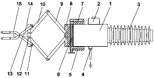
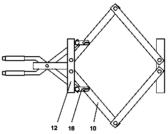
[0017] refer to Figure 1-2 , a test tool for electric equipment, including a shielding connection sleeve 1, a test sleeve 3 is arranged on the shielding connection sleeve 1, an inlet and outlet sleeve 2 is provided on one side of the shielding connection sleeve 1, and the shielding connection sleeve 1 is far away from the inlet and outlet sleeves One side of the tube 2 is provided with a grounding wire 4, and the side of the shielding connection sleeve 1 away from the test casing 3 is provided with a fixed block 5, and a threaded rod 6 is provided inside the fixed block 5, and two clamping blocks are threaded on the threaded rod 6 7, and the two clamping blocks 7 ar...


PUM


Abstract

The invention discloses a test tool for an electric power device. The test tool comprises a shielded connecting sleeve provided with a test casing tube; an inlet and outlet bushing is arranged at one side of the shielded connecting sleeve; and a ground wire is arranged at one side, far away from the inlet and outlet bushing, of the shielded connecting sleeve. A fixed block is arranged at one side, far away from the test casing tube, of the shielded connecting sleeve; a screw rod is arranged inside the fixed block; and two clamp blocks are in threaded connection to the screw rod and are clamped with the shielded connecting sleeve jointly. A first connection block is connected to one end, far away from the shielded connecting sleeve, of the fixed block; two first connecting rods are arranged symmetrically at one end, far away from the fixed block, of the first connection block and are connected to the fixed block in a rotating manner; and the second connection rod is connected to one end, far away from the fixed block, of each first connection block. The test tool has advantages of stable structure and convenient mounting and dismounting; the extension function of the test tool is realized; lots of time and energy of the staff are saved; and the test tool has the great promotion value.

Description

technical field [0001] The invention relates to the technical field of electric equipment, in particular to a test tool for electric equipment. Background technique [0002] For electrical equipment such as cable joints and switch cabinets with cable joints, transformers, etc., when conducting electrical performance tests, especially when the voltage level is high, only the voltage can be applied to the dry terminal at the other end of the cable loop with cable joints for testing. , this test method is particularly inconvenient, and the test result cannot be judged effectively in time, and the reliability of the test is low, which brings great trouble to the test. In the prior art, the voltage is directly applied to the end of the cable joint for testing, which often has the problem of insufficient safety, and the length of the test tool cannot be adjusted as required. Contents of the invention [0003] The purpose of the present invention is to solve the problem that the...

Claims


Application Information

Patent Timeline
Patent Type & Authority Patents(China)
IPC IPC(8): G01R1/04
CPCG01R1/0416
Inventor 缪武林裴启江王伟袁健耀杜晓峰
Owner DAISHAN POWER SUPPLY CO STATE GRID ZHEJIANG ELECTRIC POWER CO
Why Eureka
Try Eureka