Optical system mirror group, imaging device and electronic device

An optical system and mirror group technology, applied in optics, optical components, instruments, etc., can solve the problems of difficult product volume reduction, use restrictions, stray light intensity quality, etc. The effect of correcting off-axis aberrations

Active Publication Date: 2019-06-14
LARGAN PRECISION
View PDF13 Cites 0 Cited by
  • Summary
  • Abstract
  • Description
  • Claims
  • Application Information

AI Technical Summary

Problems solved by technology

[0003] However, in order to obtain a wide range of images, traditional wide-angle lenses often require huge lenses to receive light, and it is difficult to reduce the size of the product. This makes it difficult for traditional wide-angle lenses to meet the large viewing angle and short overall length at the same time, or the quality cannot meet the specifications due to too strong stray light. Therefore, the traditional design can no longer meet the specifications and needs of the future market.

Method used


Image

  • Optical system mirror group, imaging device and electronic device
  • Optical system mirror group, imaging device and electronic device
  • Optical system mirror group, imaging device and electronic device

Examples


no. 1 example

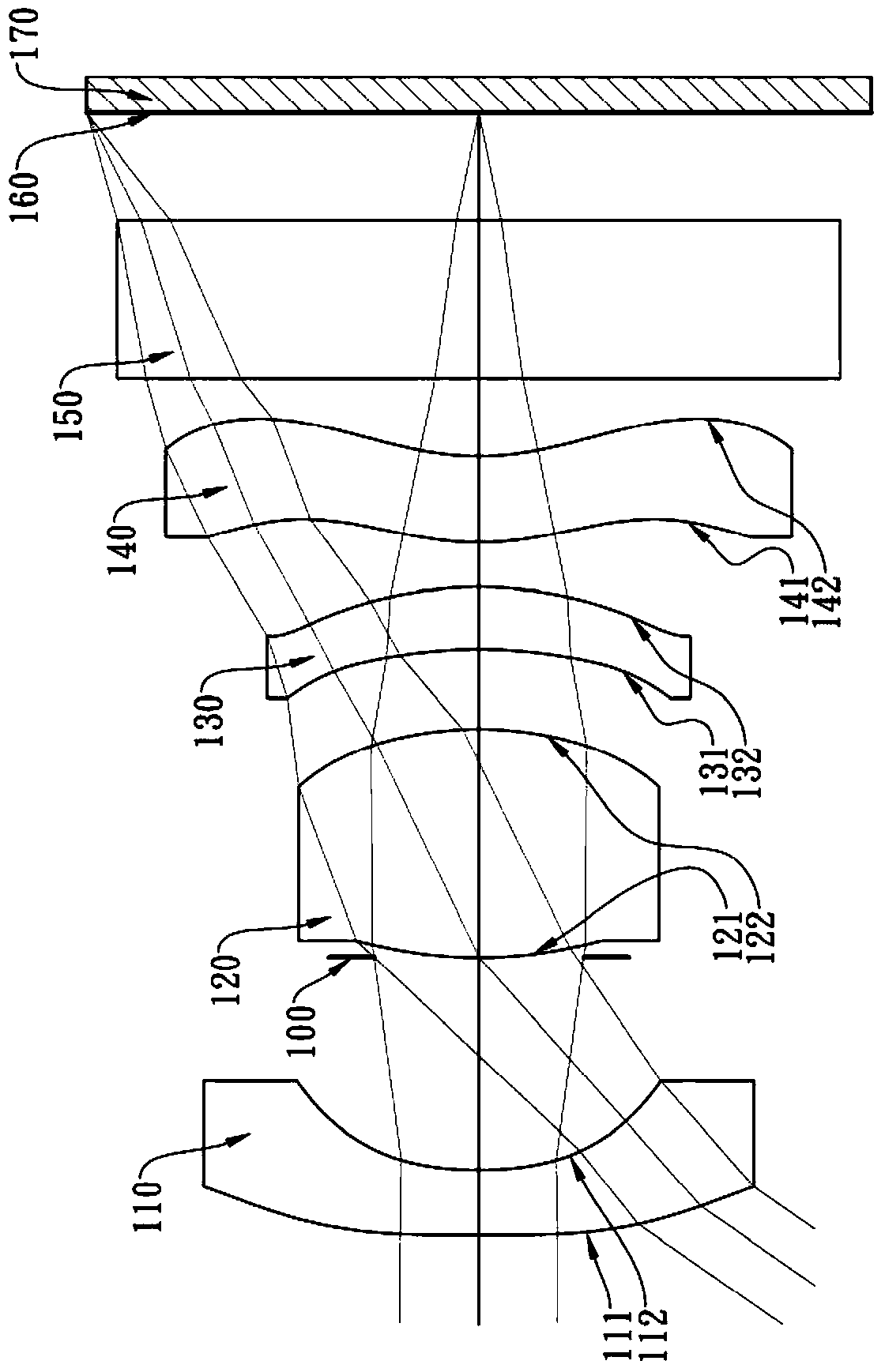
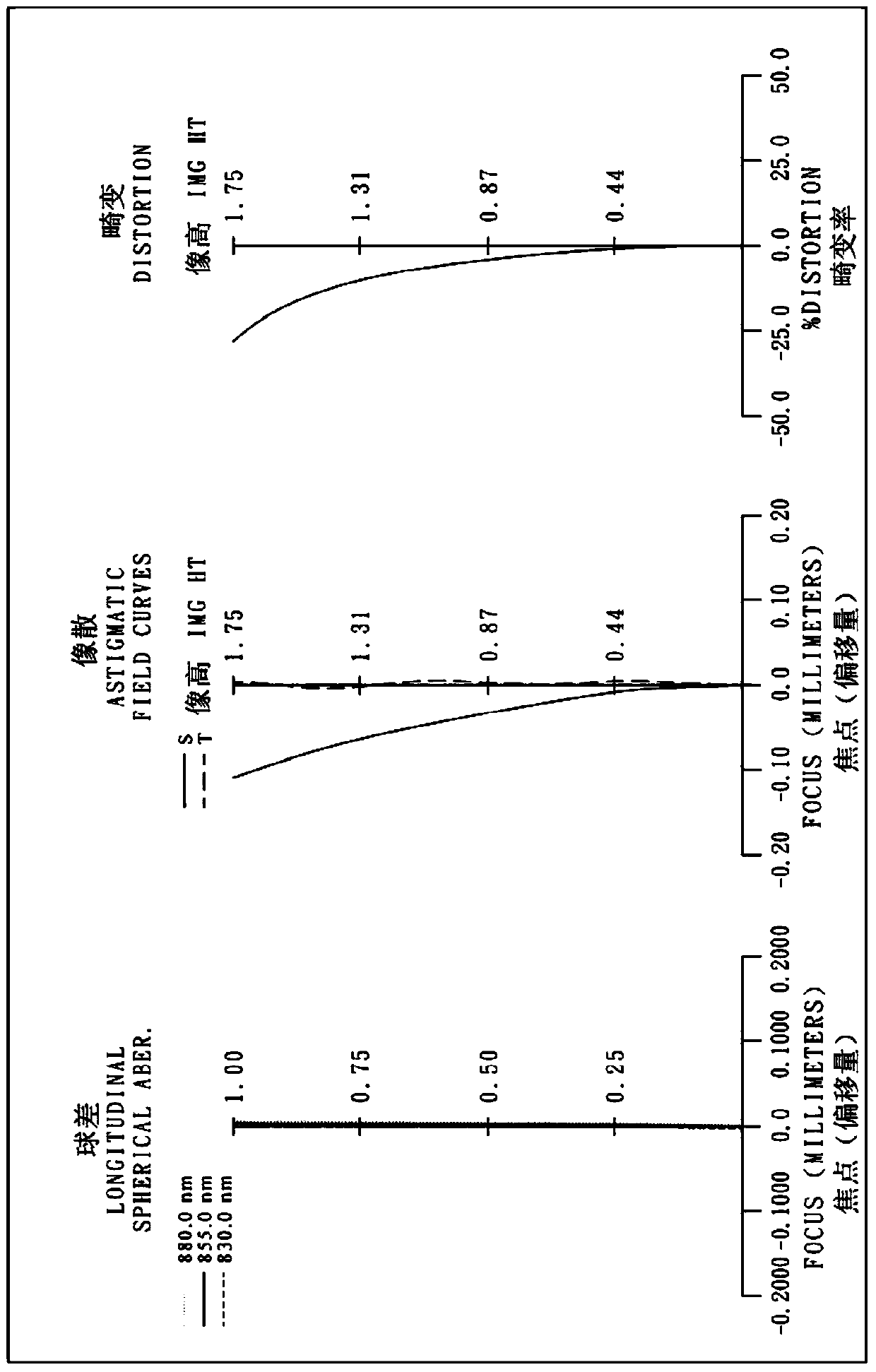
[0125] Please refer to the first embodiment of the present invention Figure 1A , for the aberration curve of the first embodiment, please refer to Figure 1B . The imaging device of the first embodiment includes an optical system lens group (not another number) and an electronic photosensitive element 170. The optical system lens group includes a first lens 110, an aperture 100, and a second lens in sequence from the object side to the image side. 120. The third lens 130 and the fourth lens 140, wherein:

[0126] The first lens 110 has a negative diopter and is made of plastic. The object side 111 is convex at the near optical axis, and the image side 112 is concave at the near optical axis. Both the object side 111 and the image side 112 are aspherical. ;

[0127] The second lens 120 has a positive diopter and is made of plastic. The object side 121 is convex at the near optical axis, and the image side 122 is convex at the near optical axis. Both the object side 121 and t...

no. 2 example

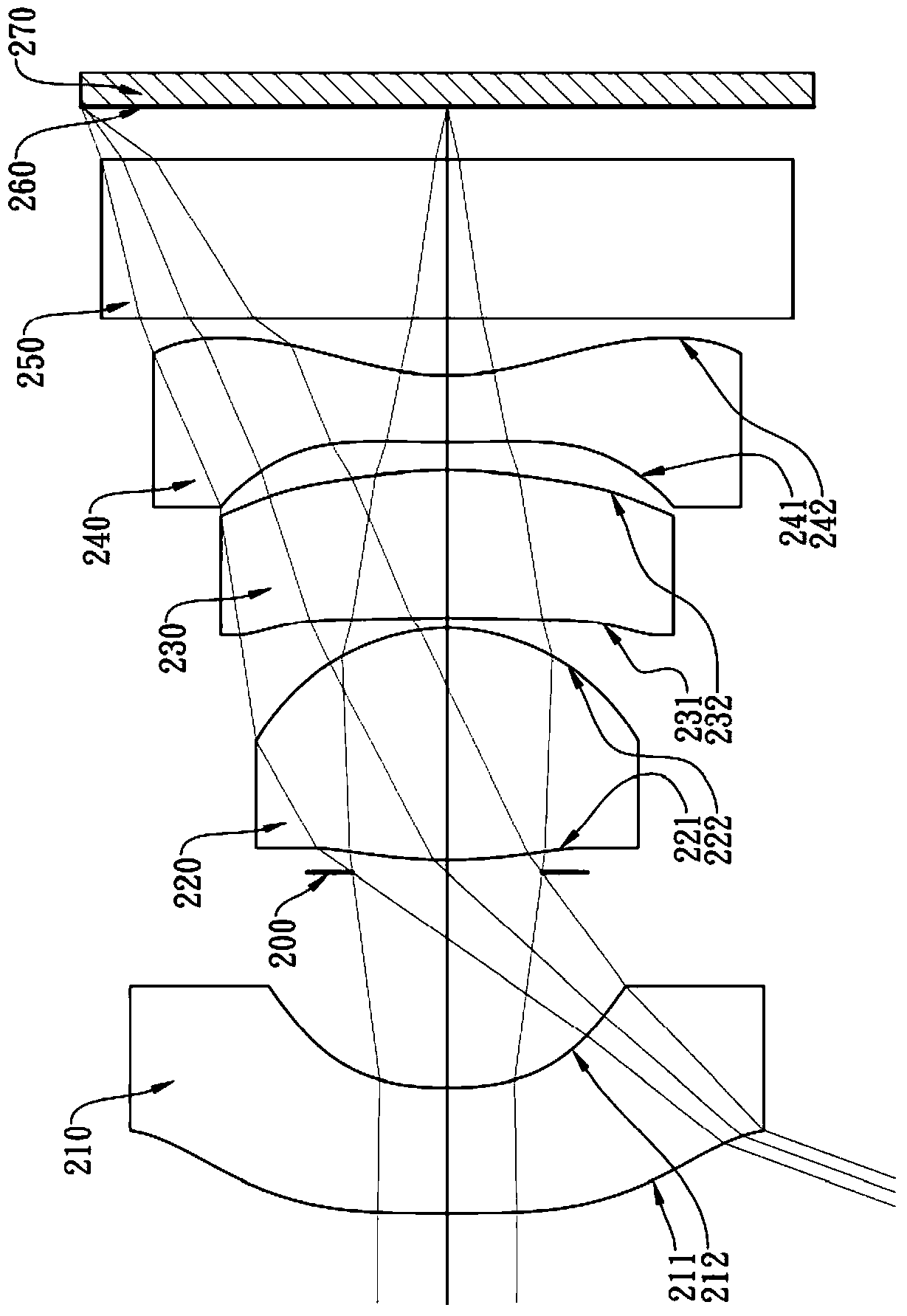
[0162] Please refer to the second embodiment of the present invention Figure 2A , for the aberration curve of the second embodiment, please refer to Figure 2B . The imaging device of the second embodiment includes an optical system lens group (not another number) and an electronic photosensitive element 270. The optical system lens group includes a first lens 210, an aperture 200, and a second lens in sequence from the object side to the image side. 220, the third lens 230 and the fourth lens 240, wherein:

[0163] The first lens 210 has a negative diopter and is made of plastic. The object side 211 is convex at the near optical axis, the image side 212 is concave at the near optical axis, and both the object side 211 and the image side 212 are aspherical. ;

[0164] The second lens 220 has a positive diopter and is made of plastic. The object side 221 is convex at the near optical axis, and the image side 222 is convex at the near optical axis. Both the object side 221 a...

no. 3 example

[0175] Please refer to the third embodiment of the present invention Figure 3A , for the aberration curve of the third embodiment, please refer to Figure 3B . The imaging device of the third embodiment includes an optical system mirror group (not another number) and an electronic photosensitive element 370. The optical system mirror group includes a first lens 310, an aperture 300, and a second lens in sequence from the object side to the image side. 320, the third lens 330 and the fourth lens 340, wherein:

[0176] The first lens 310 has a negative diopter and is made of plastic. The object side 311 is convex at the near optical axis, the image side 312 is concave at the near optical axis, and both the object side 311 and the image side 312 are aspherical. ;

[0177] The second lens 320 has a positive diopter and is made of plastic. The object side 321 is convex at the near optical axis, and the image side 322 is convex at the near optical axis. Both the object side 321 ...


PUM


Abstract

The invention provides an optical system lens set, an image capturing apparatus and an electronic apparatus. The optical system lens set sequentially comprises, from the object side to the image side, a first lens with negative diopter, of which the part of the image side close to the optical axis is a recessed surface, a second lens with positive diopter, a third lens, of which the part of the object side surface close to the optical axis is a recessed surface, and a fourth lens, of which the part of the object side surface close to the optical axis is a convex surface, the part of the image side surface close to the optical axis is a recessed surface, and the part of the image side surface away from the optical axis is a convex surface. The optical system lens set has four lenses in total. The retrofocus structure of the first lens with negative diopter allows light with large visual angle to enter into the system. The second lens with positive diopter can provide the system with sufficient gathering capability, effectively control system space and prevent the total length of lens from being too long. The third lens corrects aberrations, and the fourth lens corrects curvature of the image field. In this way, micromation of large visual angle is achieved.

Description

technical field [0001] The invention relates to an optical system mirror group and an image-taking device, in particular to an optical system mirror group and an image-taking device applicable to electronic devices. Background technique [0002] With the thinning and diversification of electronic products, the application of photography modules is becoming more and more extensive. The application range can include: various smart electronic products, driving lenses, security monitoring, 3D depth sensing devices (such as TOF cameras (Time -of-Flight Camera)), human-computer interaction platform, etc., in order to cope with its development, the lens specifications of the camera module have become more stringent, and wide viewing angles and miniaturization have become the current market trend. [0003] However, in order to obtain a wide range of images, traditional wide-angle lenses often require huge lenses to receive light, and it is difficult to reduce the size of the product...

Claims


Application Information

Patent Timeline
Patent Type & Authority Patents(China)
IPC IPC(8): G02B13/00G02B13/06G02B13/18
CPCG02B13/004G02B13/06G02B13/18
Inventor 廖凌峣黄歆璇杨舒云
Owner LARGAN PRECISION
Why Eureka
Try Eureka