
Multi-camera dynamic synchronous exposure circuit and method of FPGA-based photogrammetry system

A photogrammetry and multi-camera technology, which is applied to the components of TV systems, TVs, electrical components, etc., can solve the problems of synchronous exposure error and the inability to achieve high-precision synchronous exposure, so as to reduce office time and facilitate splicing and post-production Effects of processing and speeding up image processing

Active Publication Date: 2019-10-11
SHANDONG UNIV OF SCI & TECH
View PDF4 Cites 0 Cited by
  • Summary
  • Abstract
  • Description
  • Claims
  • Application Information

AI Technical Summary

Problems solved by technology

[0004] Traditional synchronization is that multiple cameras use the same synchronization pulse to control simultaneous exposure, without considering the mechanical differences of each camera, and the time and space of the exposure synchronization error of each camera caused by factors such as temperature, humidity and air pressure in a complex working environment. Dispersion, etc., resulting in the synchronous exposure error of this method is about 10mS, and it is impossible to achieve high-precision synchronous exposure within the microsecond level

Method used


Image

  • Multi-camera dynamic synchronous exposure circuit and method of FPGA-based photogrammetry system
  • Multi-camera dynamic synchronous exposure circuit and method of FPGA-based photogrammetry system
  • Multi-camera dynamic synchronous exposure circuit and method of FPGA-based photogrammetry system

Examples


Embodiment Construction

[0028] The present invention will be further described below in conjunction with the accompanying drawings and embodiments.

[0029] It should be pointed out that the following detailed description is exemplary and intended to provide further explanation to the present application. Unless defined otherwise, all technical and scientific terms used herein have the same meaning as commonly understood by one of ordinary skill in the art to which this application belongs.

[0030] It should be noted that the terminology used here is only for describing specific implementations, and is not intended to limit the exemplary implementations according to the present application. As used herein, unless the context clearly dictates otherwise, the singular is intended to include the plural, and it should also be understood that when the terms "comprising" and / or "comprising" are used in this specification, they mean There are features, steps, operations, means, components and / or combinatio...


PUM


Abstract

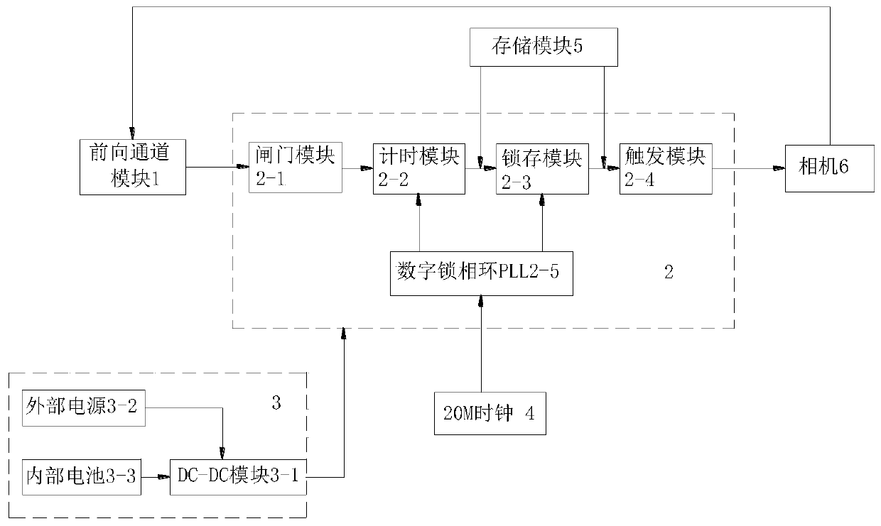
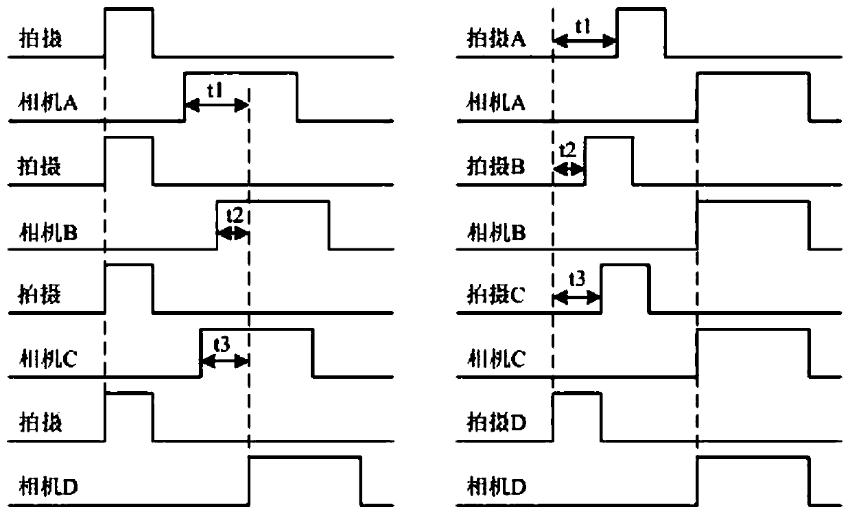
The invention discloses a multi-camera dynamic synchronous exposure circuit and method for an FPGA-based photogrammetry system. The circuit includes a forward channel module, an FPGA processing module, a power supply module and a clock module, wherein: the forward channel module provides connections for each camera The channel is connected to the FPGA processing module at the same time, and transmits the camera trigger commands collected by each camera; the FPGA processing module records the asynchronous time difference of the shutter action of each camera according to the acquired camera trigger commands, and calculates the value of the synchronization time difference, according to the synchronization time difference Value, based on the shutter action signal that arrives last, delay other trigger signals to generate synchronous camera trigger signals for each camera; the power supply module provides power for the FPGA processing module, and the clock module is configured to provide high-frequency timing for the FPGA processing module base clock signal.

Description

technical field [0001] The invention relates to an FPGA-based photogrammetry system multi-camera dynamic synchronous exposure circuit and method. Background technique [0002] If a single digital camera is used as the main sensor for image acquisition in mobile photogrammetry, the acquired digital images have a series of problems such as small image size, large number of images, long processing time, short baseline, and low elevation accuracy. Although some units at home and abroad, such as the Chinese Academy of Surveying and Mapping Sciences, have developed SWDC aerial survey cameras and special wide-angle combination cameras for UAVs, DMC aerial survey cameras in the United States, and UCD aerial survey cameras in Austria, there are still problems such as high price, large size, complex structure, and weight. Heavy and other issues. [0003] The emergence of multi-camera systems has been widely used. Compared with single cameras, multi-camera systems can obtain more accu...

Claims


Application Information

Patent Timeline
Patent Type & Authority Patents(China)
IPC IPC(8): H04N5/235H04N5/073
CPCH04N5/0733H04N23/70
Inventor 吕常智范迪石波卢秀山岳国伟刘春辉
Owner SHANDONG UNIV OF SCI & TECH
Learn More