
High-speed camera-shooting method and its system

A high-speed camera and imaging unit technology, applied in TV system components, TV system scanning details, image communication, etc., can solve the problems of inconvenient use and expensive materials, and achieve the effect of low cost and high resolution

Inactive Publication Date: 2009-05-20
PEKING UNIV
View PDF4 Cites 0 Cited by
  • Summary
  • Abstract
  • Description
  • Claims
  • Application Information

AI Technical Summary

Problems solved by technology

The exposed film can only be printed out after several processes such as developing, fixing, bleaching and drying; if it is analyzed by a computer, it must be converted into a digital image through a scanner; the entire experiment must be carried out in a darkroom, and it must be used once. It is very inconvenient to use a new negative film in the future; and this high-speed camera system must use a special chemical photosensitive film, and the material cost is also very expensive

Method used

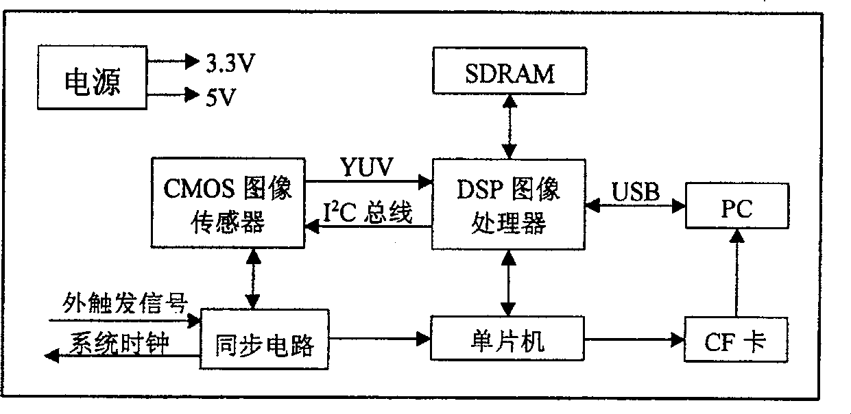
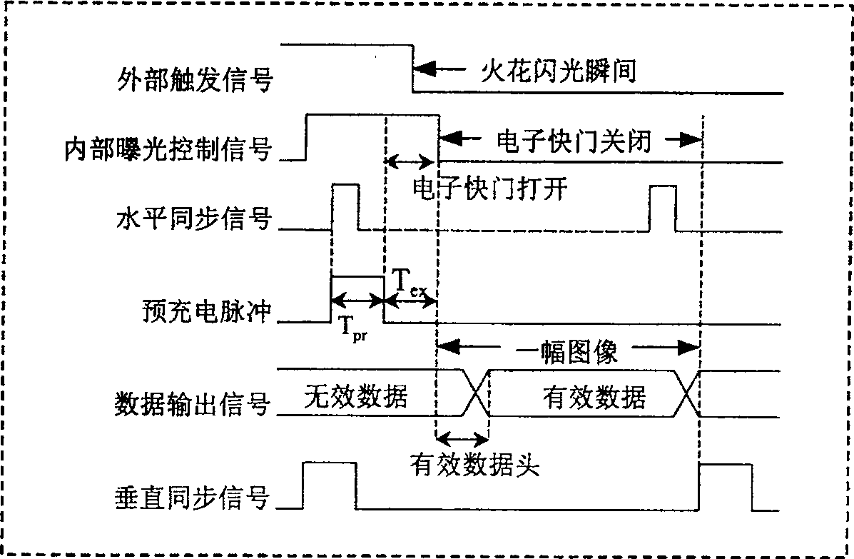

Image

  • High-speed camera-shooting method and its system
  • High-speed camera-shooting method and its system
  • High-speed camera-shooting method and its system

Examples


Embodiment Construction

[0043] The present invention will be further described below in conjunction with the accompanying drawings and embodiments.

[0044]In this embodiment, a 4×4 CMOS image sensor area array is used, and the vertical and horizontal distances between adjacent CMOS devices are both 60 mm. Each CMOS image sensor has its own image processing circuit and image storage unit, and downloads the image to the computer through its own USB interface. Each image sensor is uniformly controlled by a single power supply, and has a consistent horizontal synchronization signal HS and vertical synchronization signal VS. The whole system takes VS as the reference signal to keep the spark flash and CMOS exposure synchronized.

[0045] The imaging unit adopts a monochrome CMOS image sensor with a resolution of VGA (640×480 pixels), and the shooting result is a black and white bitmap file (.bmp) of 640×480. If you choose to compress the image, you can get a JPEG file (.jpg ). The spatial resolution i...


PUM


Abstract

This invention relates to a high-speed pick-up method and a system. The arrays composed of several CMOS image units are corresponding to spark source lattices one by one by an optical system independent of others. The CMOS imaging unit array are uniformly controlled by a single chip processor and an outer trigger circuit. After the system is reset and pre-charged, it begins couting the specific state of the time delay test system synchronous signals, when reaching to a set value, the time is delayed and signal of trigger is output the delayer begins timing, trigger pick-up signal is output, the inner exposing control circuit opens the shutter and things happen in the period of exposure, a signal of triggering spark flash is given, it flash arrays flash orderly and corresponding CMOS pixel arrays pick up orderly.

Description

Technical field: [0001] The invention relates to the technical field of high-speed imaging, in particular to a high-speed digital imaging method and system thereof. Background technique: [0002] The high-speed camera system must have a very high time resolution in order to capture some subtle changes and phenomena during high-speed motion; in addition, it also requires as many photosensitive points in the optical path as possible, that is, high spatial resolution, so that it can be used Observed motion situations are more realistic and images are clearer. [0003] Before the emergence of digital image sensors, high-speed cameras used chemical photosensitive films, which had to be replaced with new negatives after use, especially when processing images with computers, they had to be converted into digital images with digitizers such as scanners. [0004] In China, research on high-speed digital imaging technology is relatively backward. High-speed imaging equipment is most...

Claims


Application Information

Patent Timeline
Patent Type & Authority Patents(China)
IPC IPC(8): H04N5/335H04N5/232H04N3/14H04N25/00
Inventor 晏磊孙道虎赵红颖王可东赵博张罡吕书强
Owner PEKING UNIV
Learn More