
Moving Device, Moving System, Terminal Device And Method Of Controlling Moving Device

A terminal device and mobile device technology, applied in non-electric variable control, TV system components, vehicle position/route/altitude control, etc., can solve problems such as inability to track and determine the tracked object

Inactive Publication Date: 2017-10-20
CASIO COMPUTER CO LTD
View PDF5 Cites 5 Cited by
  • Summary
  • Abstract
  • Description
  • Claims
  • Application Information

AI Technical Summary

Problems solved by technology

In particular, in the above-mentioned prior art, if the flying camera is separated from the tracked object or is covered by many people, there is a problem that the tracked object cannot be identified and cannot be tracked.

Method used


Image

  • Moving Device, Moving System, Terminal Device And Method Of Controlling Moving Device
  • Moving Device, Moving System, Terminal Device And Method Of Controlling Moving Device
  • Moving Device, Moving System, Terminal Device And Method Of Controlling Moving Device

Examples


Embodiment Construction

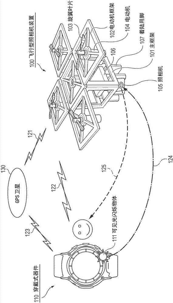
[0050] Hereinafter, modes for implementing the present invention will be described in detail with reference to the drawings. figure 1 It is a diagram showing a configuration example of an embodiment in which the mobile device of the present invention is applied to a flying camera system. This embodiment is composed of a flying camera device 100 , a wearable device 110 as a terminal device, and a visible light scintillation object 111 integrally or separately from the wearable device 110 .

[0051] In the flying camera device 100 , four motor frames 102 (support parts) are attached to the main frame 101 . The motor frame 102 can support the motor 104 , and the rotor blade 103 is fixed to a motor shaft of the motor 104 . Each rotor blade 103 forms a certain angle of attack, and can generate high lift force by rotation. The four sets of electric motors 104 and the rotor blades 103 constitute a drive propulsion unit.

[0052] A camera 105 as a camera unit is attached to the low...


PUM


Abstract

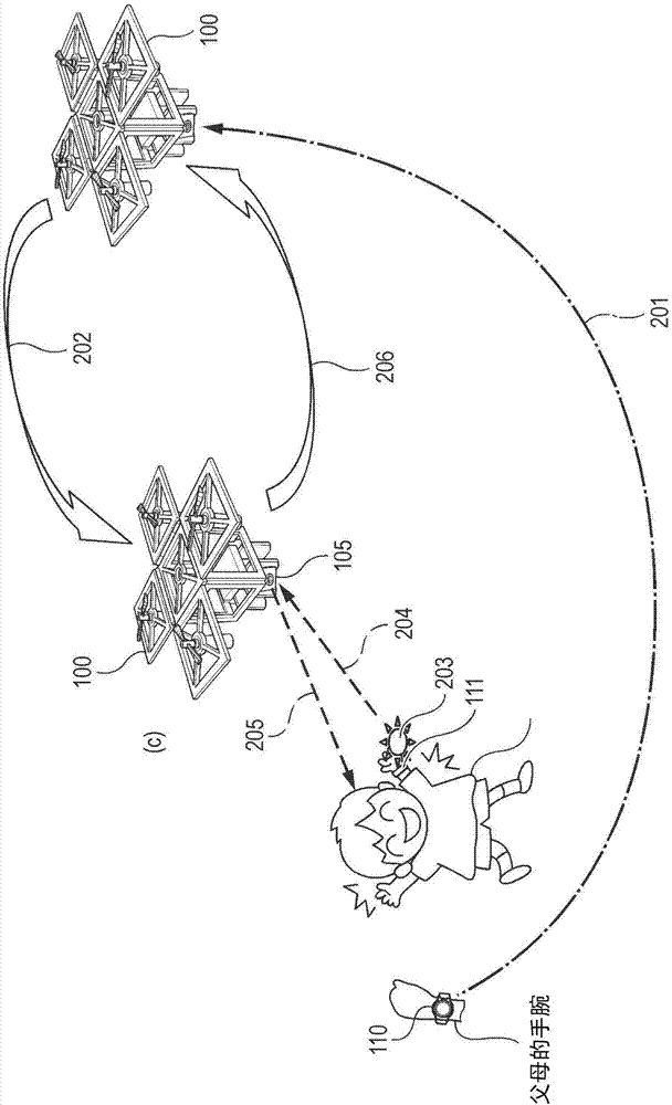
The present invention relates to a technology equipped with a camera capable of flying of a driving device, which can track automatically even the flying type camera can not capture the places of the tracked objects. A wearing device 100, based on the operation of the calling indication of a user, sends the current position of the device detected by utilizing a GPS sensor to the flying type camera device (100)(201). The flying type camera device 100 flies towards the received current position of the wearing device 110, once approaching, searches a visible light flashing object 111,for example, the flashing visible light (203, 204), at the same time, executes the face recognition processing and the shooting execution processing focused on an identified face to shoot. The flying type camera device 100 executes the processing of flying towards a stored flight starting position and returning when the shooting is ended.

Description

[0001] This application claims priority based on Japanese Patent Application No. 2016-076961 (the filing date is April 7, 2016), and all the contents of the basic application are incorporated into this application. technical field [0002] The present invention relates to a technology for mobile control of a device that moves a mobile device from a remote location to a user source. Background technique [0003] Flying cameras for aerial photography such as so-called drones are spreading. In addition, as an industrial product and a security product, a technique of tracking and photographing a subject is also known. [0004] The following technology (for example, the technology described in Patent Document 1) is known as the prior art of an aerial camera having a tracking function. The flying unit equipped with a camera recognizes a mark carried by the operator through image recognition or the like, and if the operator moves, it follows the mark and flies to capture images of...

Claims


Application Information

Patent Timeline
Patent Type & Authority Applications(China)
IPC IPC(8): H04W4/00H04W4/02H04M1/725G08C17/02G01S19/15B64C27/08B64D47/08G06V20/13G06V20/17
CPCG01S19/15G08C17/02H04W4/025H04M1/72412H04M1/72415B64U2101/30B64U10/14G05D1/0094G03B17/561H04N7/185G03B15/006G06V20/13G06V20/17H04N23/66H04N23/611H04N23/667B64U2201/00H04B5/72G06V40/172H04N23/56B64U2201/104H04N7/183
Inventor 冈田健
Owner CASIO COMPUTER CO LTD
Learn More