Water cup

A water cup and cup body technology, which is applied in the field of water cups, can solve problems such as potential safety hazards, unstable power supply connections, and power failure of the cup body, so as to achieve safe and stable power supply and increase the safety of electricity consumption

Inactive Publication Date: 2017-10-24
章璐
View PDF5 Cites 4 Cited by
  • Summary
  • Abstract
  • Description
  • Claims
  • Application Information

AI Technical Summary

Problems solved by technology

[0002] At present, boiling water cups are widely used. When using the boiling water cups, they need to be powered on first. The cup body is basically powered on by directly inserting the plugs connected to it into the power connection concave holes of the power transmission base, and the power transmission base is connected to the mains. It is always in the power-on state. Although this matching method is relatively simple and convenient to operate, the length of the cable between the post and the cup is different. After the post is inserted into the concave hole of the UMC, there is no other locking device for the post. Locking, when the cable is accidentally kicked and bumped, it will cause the post to be detached from the concave hole of the UMC, resulting in a sudden power failure of the cup, and in severe cases, it will directly cause damage to the cup. Therefore, the existing plug There is an unstable power supply connection between the column and the UMC concave hole. In addition, when the cup is not in use, the post is often pulled out from the UMC concave hole, which will cause the UMC concave hole to be exposed. It is a big safety hazard, and a large force needs to be applied when the post is pulled out from the UMC concave hole, which is not easy to operate

Method used


Image

  • Water cup
  • Water cup
  • Water cup

Examples


Embodiment Construction

[0020] The preferred embodiments of the present invention will be described in detail below in conjunction with the accompanying drawings, so that the advantages and features of the present invention can be more easily understood by those skilled in the art, so as to define the protection scope of the present invention more clearly.

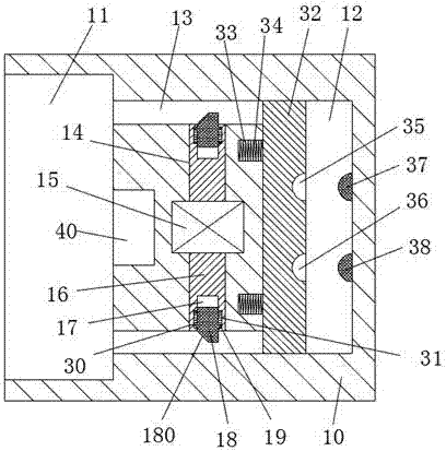
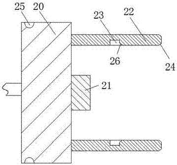
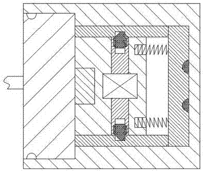
[0021] refer to Figure 1-5 The shown water cup includes a cup body 50, a power connection handle 20 fixedly connected to the cup body 50 through a cable, and a power transmission seat 10 mated with the power connection handle 20. The left end of the cup body 50 is provided with a Cup mouth 51, arm handle 52 is provided on the right end surface, and cup cover 53 is arranged on the upper end that can be opened and closed. The front and rear sides of the column 21 are respectively provided with two insertion rods 22 correspondingly, and a lock slot 23 is arranged on the inner end surface of each of the two insertion rods 22 , and the right end of e...


PUM


Abstract

The invention discloses a water cup. The water cup comprises a cup body, an electricity connection handle which is fixedly connected to the cup body through a cable and a power transmission seat which is in cooperation connection with the electricity connection handle; a cup port is arranged on an left end surface of the cup body, a handle is arranged on a right end surface, and a cup cover is arranged on an upper top in a manner of opening and closing; an inserting column is arranged in the middle portion of the right end surface of the electricity connection handle; two inserting rods are correspondingly arranged on the front side and on the back side of the inserting column and are arranged on the right end surface of the electricity connection handle; a position locking groove is arranged on the inner side end surface of each inserting rod; a first guiding surface is arranged on the inner side of the right end of each position locking groove; and a second guiding surface is arranged on the outer side of the right end surface of each inserting rod. The water cup is simple in structure and high in power supply stability and effectively reduces electrocution accidents during water boiling and guarantees people's safety. The unlocking of the electricity connection handle is realized through control of a driving machine. The unlocking of the electricity connection handle and push-out disconnection of the inserting rods from cooperation connection with an electricity connection recessed hole are realized. The water cup is simple and convenient in power on and power off operations.

Description

technical field [0001] The invention relates to the field of water cups, in particular to a water cup. Background technique [0002] At present, boiling water cups are widely used. When using the boiling water cups, they need to be powered on first. The cup body is basically powered on by directly inserting the plugs connected to it into the power connection concave holes of the power transmission base, and the power transmission base is connected to the mains. It is always in the power-on state. Although this matching method is relatively simple and convenient to operate, the length of the cable between the post and the cup is different. After the post is inserted into the concave hole of the UMC, there is no other locking device for the post. Locking, when the cable is accidentally kicked and bumped, it will cause the post to be detached from the concave hole of the UMC, resulting in a sudden power failure of the cup, and in severe cases, it will directly cause damage to t...

Claims


Application Information

Patent Timeline
Patent Type & Authority Applications(China)
IPC IPC(8): A47J27/21A47J36/24A47G19/22
CPCA47J27/21008A47G19/2205A47J27/21166A47J36/2466
Inventor 章璐
Owner 章璐
Why Eureka
Try Eureka