Energy storage quick-heating drinking apparatus

A drinking water equipment and fast heating technology, applied in beverage preparation devices, kitchen utensils, home utensils, etc., can solve the problems of breeding bacteria, unable to solve secondary pollution, unable to produce warm water, etc., to prevent safety incidents and improve water quality assurance , The effect of preventing scale accumulation

Inactive Publication Date: 2017-10-24
HAINAN LITREE PURIFYING TECH CO LTD
View PDF6 Cites 5 Cited by
  • Summary
  • Abstract
  • Description
  • Claims
  • Application Information

AI Technical Summary

Problems solved by technology

[0002] At present, the types of large-scale commercial water dispensers in the market are mainly divided into heat-exchange energy-saving water dispensers and step-by-step water dispensers. Among them, heat-exchange energy-saving water dispensers are devices that use the principle of heat exchange to heat water. And connecting such equipment generally has the following disadvantages: 1) it is easy to form thousands of boiling water and yin and yang water; 2) it is directly heated in the water storage tank, and the pipeline is formed, which breeds bacteria and easily produces secondary pollution, which affects the health of the drinker; , most manufacturers use the method of emptying the water tank overnight to reduce the harm of secondary pollution, but it cannot be completely avoided, and it also wastes a lot of water resources
The step-by-step water dispenser controls the water intake and heating time through frequency conversion, and adopts step-by-step heating technology, without the generation of thousands of boiling water and yin and yang water, but it cannot produce warm water, which is difficult to meet the needs of the market, especially Drinking water requirements for primary and secondary school campuses also cannot solve the problem of secondary pollution

Method used


Image

  • Energy storage quick-heating drinking apparatus
  • Energy storage quick-heating drinking apparatus

Examples


Embodiment Construction

[0077] The present invention will be described in detail below in conjunction with the accompanying drawings.

[0078] It should be noted that when an element is considered to be "connected" to another element, it may be directly connected to the other element or there may be intervening elements at the same time.

[0079] Unless defined otherwise, all technical and scientific terms used herein have the same meaning as commonly understood by one of ordinary skill in the art to which this invention belongs. The terms used herein in the description of the present invention are for the purpose of describing the embodiments only, and are not intended to limit the present invention. As used herein, "and / or" includes any and all combinations of one or more of the associated listed items.

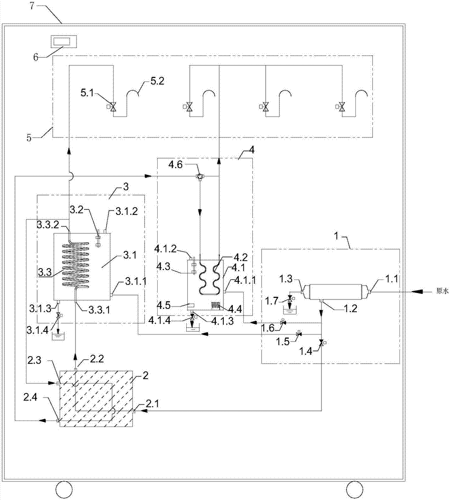
[0080] Such as figure 1 As shown, the energy storage quick-heat drinking water equipment of the present invention includes: a purification device 1, a heat exchange device 2, an energy storage h...


PUM


Abstract

The invention relates to an energy storage quick-heating drinking apparatus, comprising a purifying device, a heat exchange device, an energy storage type heating device, a faucet assembly, a pipeline assembly, a system control device for controlling the whole drinking apparatus, and a drinking apparatus main body. The energy storage type heating device comprises a heating water tank for storing water, and a heating pipeline disposed in the heating water tank, and water in the heating water tank is used for heating purified water in the heating pipeline to boiled water. The purifying device is used for providing the heating pipeline with the purified water. The heat exchange device is used for cooling the boiled water from the energy storage type heating device. The boiled water flowing out from the heating pipeline is divided into two paths, the hot water of the first path is directly supplied to a faucet of the faucet assembly, the hot water of the second path is cooled by the heat exchange device and supplied to the faucet of the faucet assembly, so that drinking water directly passes through the pipeline without passing through the heating water tank, secondary pollution can be prevented, and re-boiled water and a mixture of unboiled water and boiled water can also be prevented.

Description

technical field [0001] The invention relates to the field of drinking water equipment, in particular to an energy storage instant hot drinking water equipment. Background technique [0002] At present, the types of large-scale commercial water dispensers in the market are mainly divided into heat-exchange energy-saving water dispensers and step-by-step water dispensers. Among them, heat-exchange energy-saving water dispensers are devices that use the principle of heat exchange to heat water. And connecting such equipment generally has the following disadvantages: 1) it is easy to form thousands of boiling water and yin and yang water; 2) it is directly heated in the water storage tank, and the pipeline is formed, which breeds bacteria and easily produces secondary pollution, which affects the health of the drinker; , Most manufacturers use the way of emptying the water tank overnight to reduce the harm of secondary pollution, but it cannot be completely avoided, and it also ...

Claims


Application Information

Patent Timeline
Patent Type & Authority Applications(China)
IPC IPC(8): A47J31/00A47J31/46A47J31/56A47J31/60
Inventor 陈清陈忱陈良刚
Owner HAINAN LITREE PURIFYING TECH CO LTD
Why Eureka
Try Eureka