High-temperature dust removing device

A high-temperature dust removal and box technology, applied in transportation and packaging, dispersed particle filtration, gas treatment, etc., can solve the problems of unfavorable energy, high operating cost, shortened service life, etc., and achieve thermal fatigue resistance, porosity, dust removal and denitrification Integration, the effect of increasing dust removal efficiency

Inactive Publication Date: 2017-10-24
萍乡市普天高科实业有限公司
View PDF4 Cites 6 Cited by
  • Summary
  • Abstract
  • Description
  • Claims
  • Application Information

AI Technical Summary

Problems solved by technology

At present, most dust removal devices on the market mainly use bag dust removal, electric dust removal and water film dust removal. Most of these dust removal methods cannot be treated at high temperatures, which is not conducive to the effective use of energy, and the loss of heat energy is very serious, and there are also disadvantages such as high operating costs.
Although the existing high-temperature dust removal pipe can perform high-temperature dust removal, because the filter plate is manufactured using external pressure molding technology, thermal fatigue will occur after repeated use, thereby shortening its service life, and its small porosity results in low dust removal efficiency

Method used


Image

  • High-temperature dust removing device

Examples


Embodiment 2

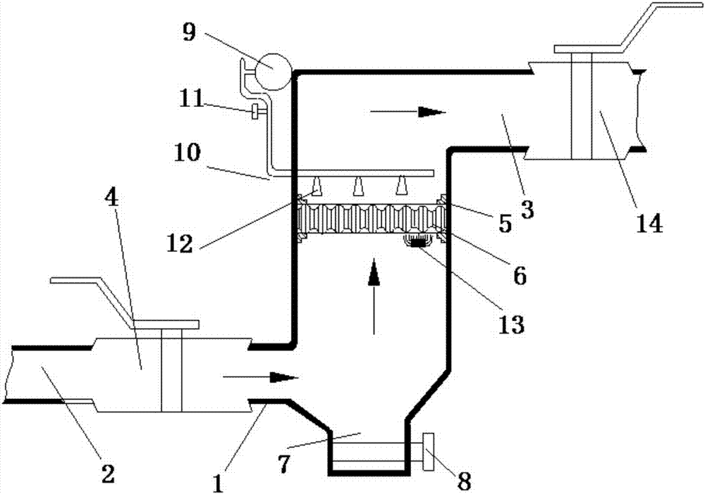
[0014] Preferred embodiment 2, this preferred embodiment discloses a high-temperature dust removal pipe, which is basically the same as the device described in the preferred embodiment 1, the difference is that: the box body 1 is also equipped with a back-blowing soot assembly, and the back-blowing soot The soot blowing assembly includes an air pump 9 arranged outside the box 1, a conduit 10 and a regulating valve 11 connected to the conduit 9. One end of the conduit 10 is connected to the air pump 9, and the other end is connected to the box 1. At the same time, the conduit 10 is provided with a blowing port 12. The blowing port 12 partially extends into the ceramic fiber filter plate. Use a small air pump to provide high-pressure gas, and the gas will lead to the ceramic fiber filter plate 6 through the blowing port 12 on the conduit 10, and the dust attached to the ceramic fiber filter plate 6 will be blown off to prevent excessive accumulation on the ceramic fiber filter pl...

Embodiment 3

[0015] Preferred embodiment 3, this preferred embodiment discloses a high-temperature dust removal pipe, which is basically the same as the device described in the preferred embodiment 2, the difference is that: the fixed seat 5 is also on the side close to the air inlet 2 A soot cleaner 13 is provided, and the soot remover 13 is a vibrating soot cleaner, a sonic soot cleaner, a steam soot remover or an electric brush soot remover, and the soot remover 13 can remove the dust attached to the ceramic fiber filter plate , to prevent the ceramic fiber filter plate from clogging due to excessive dust, and achieve the same effect as that of the preferred embodiment 2. A soot remover 13 can be set beside each ceramic fiber filter plate 6, or only a soot remover 13 is set on the ceramic fiber filter plate 6 closest to the air inlet 2. Preferably, the soot cleaner 13 is a vibrating soot cleaner, because the dust particles in the gas to be treated are very small, and the dust on the cer...


PUM


Abstract

The invention discloses a high-temperature dust removing device. The device comprises a box body, one side of the box body is connected with an air inlet, and the other side is connected with an air outlet; a first air-pressure regulating valve is arranged between the air inlet and the box body, and a second air-pressure regulating valve is arranged between the air outlet and the box body; fixed seats are arranged in the box body, and a ceramic fiber filter layer clamping sleeve with catalysts is arranged between the fixed seats; a ceramic fiber filter layer is formed by splicing multiple ceramic fiber plates, and the ceramic fiber filter plates are made by an isostatic pressing molding technology; both the upper and lower surfaces of the ceramic fiber filter layer are a cambered-surface wave shape, the side, close to the air inlet, of the box body is provided with an ash zone, and the ash discharging pipe of the lower end of the ash zone is provided with an ash discharging valve. According to the high-temperature dust removing device, the isostatic pressing molding technology is used, the catalysts are combined to produce the ceramic fiber filter plates at the same time, and therefore the integration of dust removing and denitration is achieved.

Description

technical field [0001] The invention relates to the field of flue gas dust removal, in particular to a high-temperature dust removal device. Background technique [0002] With the development of science and technology, the country has gradually increased the intensity of environmental protection, and many industries that use coal, oil, gas, etc. as fuels have increasing requirements for high-temperature flue gas dust removal. At present, most dust removal devices on the market mainly use bag dust removal, electric dust removal and water film dust removal. Most of these dust removal methods cannot be processed at high temperature, which is not conducive to the effective use of energy, and the loss of heat energy is very serious, and there are also disadvantages such as high operating costs. Although the existing high-temperature dust removal pipe can perform high-temperature dust removal, because the filter plate is manufactured using external pressure molding technology, the...

Claims


Application Information

Patent Timeline
Patent Type & Authority Applications(China)
IPC IPC(8): B01D46/10B01D46/00B01D53/88
CPCB01D46/0001B01D46/0027B01D46/10B01D53/88B01D2258/0283B01D46/72B01D46/76
Inventor 黄乃乔袁明辉刘绍辉
Owner 萍乡市普天高科实业有限公司
Why Eureka
Try Eureka