injection mold

A technology for injection molds and mold bases, which is applied in the field of molds, can solve the problems of increased mold cost, mold maintenance difficulty, design difficulty, and many mold accessories, and achieves the effects of convenient installation and maintenance, smooth demoulding, and simple mold structure

Active Publication Date: 2019-06-11
BAODING WEIYI AUTOMOBILE CO LTD
View PDF2 Cites 0 Cited by
  • Summary
  • Abstract
  • Description
  • Claims
  • Application Information

AI Technical Summary

Problems solved by technology

This kind of structural design is difficult, there are many mold parts, installation is troublesome, and the cost of the mold and the difficulty of subsequent mold maintenance are also greatly increased.

Method used


Image

  • injection mold
  • injection mold
  • injection mold

Examples


Embodiment Construction

[0036] It should be noted that, in the case of no conflict, the embodiments of the present invention and the features in the embodiments can be combined with each other.

[0037] The present invention will be described in detail below with reference to the accompanying drawings and examples.

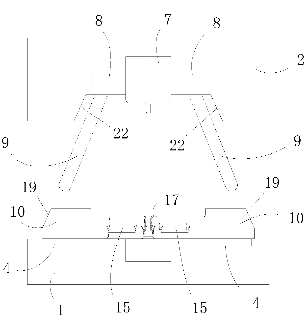
[0038] This embodiment relates to an injection mold, which is used for injection molding a product with an undercut structure on the side, and can realize the smooth demoulding of the mold after the injection molding is completed. Such as figure 1 As shown in , the injection mold includes a lower mold base 1, and an upper mold base 2 located above the lower mold base 1, and the upper mold base 2 can move relative to the lower mold base 1 to inject products. On the lower mold base 1, a slide block 10 is provided, and a slanted top 15 is arranged in the slide block 10. When the upper mold base 2 moves relative to the lower mold base 1, a sliding block 10 for driving the slide block 10 is ...


PUM


Abstract

The invention provides an injection mould comprising a lower mould seat and an upper mould seat arranged above the lower mould seat. The upper mould seat can move relative to the lower mould seat so as to conduct product injection. The injection mould further comprises sliding blocks slidably arranged on the lower mould seat, a driving mechanism arranged between the upper mould seat and the sliding blocks, lifters contained in the sliding blocks, power bearing parts arranged on the lifters, power transmitting parts arranged on the sliding blocks and guiding parts arranged on the lower mould seat. According to the injection mould, an inverted buckled structure of the side face of a workpiece can be formed in mould assembly injection, power used for movement of the lifters is provided by the upper mould seat, the mould structure can be simplified, and the stability of the mould is improved; and meanwhile, through arrangement of the guiding parts, it is also ensured that the workpiece can be separated from the mould smoothly.

Description

technical field [0001] The invention relates to the technical field of molds, in particular to an injection mold. Background technique [0002] During the design process of injection molds, it is often encountered that there are undercuts on the products, so that the products cannot be directly removed from the mold. In order to realize the demoulding of the products, the existing injection molds are usually equipped with inclined top or slider structures. For example, for products with an undercut structure on the side, the slider structure generally adopts an inclined top inside the slider, and a spring is added at the bottom of the inclined top to solve the problem of product demoulding. However, the spring in this structure is prone to fatigue failure under long-term and high-frequency use, and this situation is not easy to be found in the injection molding production process, so that there is a risk of damage to the inclined roof and mold core. [0003] In addition to ...

Claims


Application Information

Patent Timeline
Patent Type & Authority Patents(China)
IPC IPC(8): B29C45/33B29C45/40
CPCB29C45/332B29C45/4005
Inventor 吕龙福覃柱人金孟许振华祖润青
Owner BAODING WEIYI AUTOMOBILE CO LTD
Why Eureka
Try Eureka